Information pump assy, injecti
Nozzle:
0935008100
Rating:
KIT List:
| Governor assy, mec | 1908900720 |
| Pump assy, fuel fe | 1922900070 |
| Body assy, injecti | 1904400380 |
Components :
| 001. | PUMP ASSY, INJECTI | 09200-05590 |
| 002. | GOVERNOR ASSY, MEC | 09130-07671 |
| 003. | COMPENSATOR SUB-AS | 19260-01820 |
| 004. | TIMER ASSY, AUTOMA | 09180-04230 |
| 005. | PUMP ASSY, FUEL FE | 09210-03161 |
| 006. | COUPLING ASSY | 09250-01080 |
| 007. | BODY ASSY, INJECTI | 19010-02010 |
| 008. | COVER, BEARING | 09020-10430 |
Scheme ###:
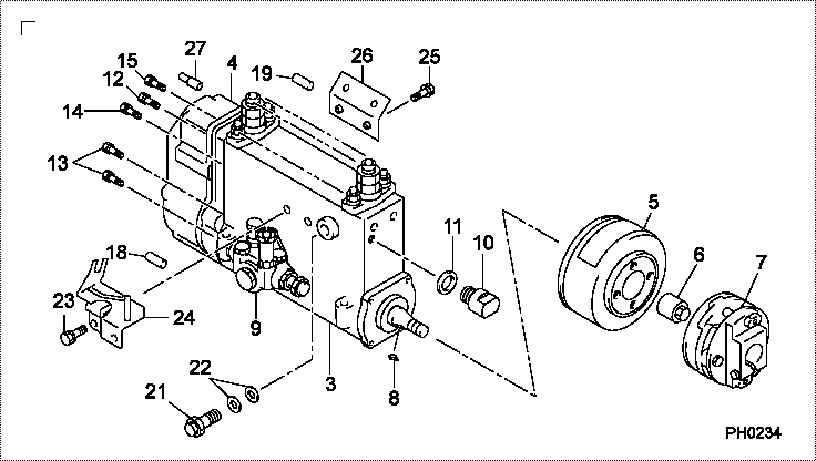
| 000. | [01] | 09200-05590 | PUMP ASSY, INJECTI | 22010-E0150 |
| 003. | [01] | 19010-02010 | BODY ASSY, INJECTI | |
| 004. | [01] | 09130-07671 | GOVERNOR ASSY, MEC | |
| 005. | [01] | 09180-04230 | TIMER ASSY, AUTOMA | |
| 006. | [01] | 09001-20340 | NUT, TIMER ROUND | S2282-52240-A |
| 007. | [01] | 09250-01080 | COUPLING ASSY | S2261-01880-A |
| 008. | [01] | 90458-05750 | KEY, WOODRUFF | S2289-11070-A |
| 009. | [01] | 09210-03161 | PUMP ASSY, FUEL FE | S2257-01830-A |
| 010. | [01] | 09001-80381 | COVER, CONTROL RAC | S2211-41200-A |
| 011. | [01] | 94901-81550 | WASHER, COPPER PLA | SL722-02215 |
| 012. | [01] | 94904-76900 | BOLT, W/WASHER | S2281-53230-A |
| 013. | [04] | 94904-76890 | BOLT, W/WASHER | S2281-53210-A |
| 014. | [01] | 94904-76910 | BOLT, W/WASHER | S2281-53240-A |
| 015. | [02] | 94904-76880 | BOLT, W/WASHER | S2281-53320-A |
| 018. | [01] | 09028-50030 | CAP | S2232-31210-A |
| 019. | [01] | 09028-50050 | CAP | S2232-31430-A |
| 021. | [01] | 09031-00360 | VALVE ASSY, OVERFL | S2210-71480-A |
| 022. | [02] | 94901-02490 | WASHER | S2287-71100-A |
| 023. | [02] | 91418-08161 | BOLT, W/WASHER | S2281-53370-A |
| 024. | [01] | 09069-01020 | BRACKET SUB-ASSY, | S2234-37470-A |
| 025. | [02] | 91808-08201 | BOLT, FLANGE | S2281-53390-A |
| 026. | [01] | 09045-30230 | STAY, INJECTION PU | S1140-91540-A |
| 027. | [01] | 09028-50030 | CAP | S2232-31210-A |
Include in #3:
09200-05590
as PUMP ASSY, INJECTI
Cross reference number
| Part num | Firm num | Firm | Name |
| 09200-05590 | 22010-E015 | PUMP ASSY, INJECTI | |
| 22010-E0150 | HINO | PUMP ASSY, INJECTI |
Information:
1. Remove the fuel injection nozzle assembly, and put the piston on TDC (top dead center) for the respective cylinder for which the valve stem seal and O-ring seals are to be removed.2. Install air chuck adapter (2). Fasten a pressure air source to pressurize the cylinder.3. Use tooling (A) to compress the valve springs. Use magnet bar (1) to hold the keepers.4. Remove tool (A), and remove the valve springs and retainer. 5. Remove exhaust valve O-ring seal (3) and inlet valve guide seal (4).
Do not release air pressure in the cylinder until the valve springs and retainer have been installed. Failure to do so will let the valve fall into the top of the piston. If the piston is not at TDC (top dead center) the valve can fall into the cylinder making cylinder head removal necessary.
Install Valve Guide Seals
1. Install spring seating washer (1). 2. Put clean engine oil on the part of valve guide seal (2) that makes contact with the valve stem. Install valve guide seal (2).
The closed coil of the spring must be toward the cylinder rod.
3. Put inner and outer springs (4) and retainer (3) in position.
The locks can be thrown from the valve when the compressor is released if they are not in their correct position on the valve stem.
4. Use tool (A) to compress the valve springs so the keepers can be installed.5. Use tool (B) to install the keepers.6. Repeat Steps 1-4 for O-ring seals (5) on the exhaust valve.7. Move the piston off T.D.C. (top dead center) and tap the valve spring retainer with a soft hammer to be sure the retainers are properly seated.8. Install the fuel injection nozzle assembly.End By:a. install rocker shaft and push rods