Information pump assy, injecti
Nozzle:
0935008100
Rating:
KIT List:
| Governor assy, mec | 1908900720 |
| Pump assy, fuel fe | 1922900070 |
| Body assy, injecti | 1904400380 |
Components :
| 001. | PUMP ASSY, INJECTI | 09200-05580 |
| 002. | GOVERNOR ASSY, MEC | 09130-07661 |
| 003. | COMPENSATOR SUB-AS | 19260-01810 |
| 004. | TIMER ASSY, AUTOMA | 09180-04230 |
| 005. | PUMP ASSY, FUEL FE | 09210-03161 |
| 006. | COUPLING ASSY | 09250-01080 |
| 007. | BODY ASSY, INJECTI | 19010-02010 |
| 008. | COVER, BEARING | 09020-10430 |
Scheme ###:
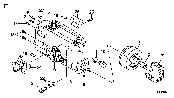
| 000. | [01] | 09200-05580 | PUMP ASSY, INJECTI | 22010-E0140 |
| 003. | [01] | 19010-02010 | BODY ASSY, INJECTI | |
| 004. | [01] | 09130-07661 | GOVERNOR ASSY, MEC | |
| 005. | [01] | 09180-04230 | TIMER ASSY, AUTOMA | |
| 006. | [01] | 09001-20340 | NUT, TIMER ROUND | S2282-52240-A |
| 007. | [01] | 09250-01080 | COUPLING ASSY | S2261-01880-A |
| 008. | [01] | 90458-05750 | KEY, WOODRUFF | S2289-11070-A |
| 009. | [01] | 09210-03161 | PUMP ASSY, FUEL FE | S2257-01830-A |
| 010. | [01] | 09001-80381 | COVER, CONTROL RAC | S2211-41200-A |
| 011. | [01] | 94901-81550 | WASHER, COPPER PLA | SL722-02215 |
| 012. | [01] | 94904-76900 | BOLT, W/WASHER | S2281-53230-A |
| 013. | [04] | 94904-76890 | BOLT, W/WASHER | S2281-53210-A |
| 014. | [01] | 94904-76910 | BOLT, W/WASHER | S2281-53240-A |
| 015. | [02] | 94904-76880 | BOLT, W/WASHER | S2281-53320-A |
| 018. | [01] | 09028-50030 | CAP | S2232-31210-A |
| 019. | [01] | 09028-50050 | CAP | S2232-31430-A |
| 021. | [01] | 09031-00360 | VALVE ASSY, OVERFL | S2210-71480-A |
| 022. | [02] | 94901-02490 | WASHER | S2287-71100-A |
| 023. | [02] | 91418-08161 | BOLT, W/WASHER | S2281-53370-A |
| 024. | [01] | 09069-01020 | BRACKET SUB-ASSY, | S2234-37470-A |
| 025. | [02] | 91808-08201 | BOLT, FLANGE | S2281-53390-A |
| 026. | [01] | 09045-30230 | STAY, INJECTION PU | S1140-91540-A |
| 027. | [01] | 09028-50030 | CAP | S2232-31210-A |
Include in #3:
09200-05580
as PUMP ASSY, INJECTI
Cross reference number
| Part num | Firm num | Firm | Name |
| 09200-05580 | 22010-E014 | PUMP ASSY, INJECTI | |
| 22010-E0140 | HINO | PUMP ASSY, INJECTI |
Information:
1. Remove circlip (1) and the washer from each end of the rocker shaft. 2. Put identification marks on the rocker arms, brackets and springs as to their location on the rocker shaft. Remove rocker arms (2), brackets (3) and springs (4) from each side of the rocker shaft.3. Remove screw (5) and rocker shaft oil feed connection (6). 4. Remove nut (7) and adjusting screw (8) from the rocker arm.5. Measure the bore of the bearings in each of the rocker arms. The bore must be 19.06 to 19.10 mm (.7505 to .7520 in.).6. Measure the diameter of the rocker shaft at each of the rocker arm locations. The diameter must be 19.01 to 19.04 mm (.7485 to .7495 in.). The maximum permissible clearance between the rocker arm bearings and shaft is 0.13 mm (.005 in.).7. If a replacement is needed, remove bushing (9) with tooling (A) and a press.Assemble Rocker Shaft
1. If a replacement was needed, make an alignment of oil hole (1) in the bushing with the oil hole in the rocker arm. Install new bushing (3) in the rocker arm with tooling (A) and a press. Check the bore dimension of the bushing in the rocker arm after installation. It must be 19.06 to 19.10 mm (.7505 to .7520 in.).
Do not turn the adjusting screw too far into the rocker arms. Damage to the valve can be the result after the rocker shaft and push rods have been installed in the engine.
2. Install adjusting screw (4) and nut (2) in the rocker arm. 3. Slide oil feed connection (9) on the rocker shaft. Install bolt (5) that holds it in place.4. Install springs (6), brackets (7) and rocker arms (8) in their original positions. 5. Install washer (11) and circlip (10) on each end of the rocker shaft.End By:a. install rocker shaft and push rods