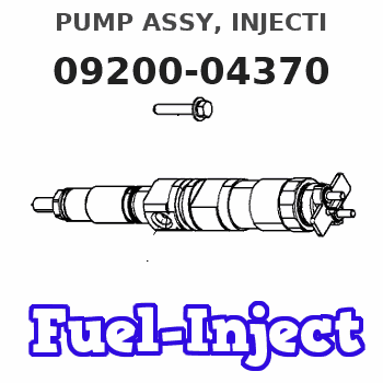
Information pump assy, injecti
Nozzle:
0935003840
Rating:
KIT List:
| Pump assy, fuel fe | 1922900060 |
| Body assy, injecti | 1904400300 |
| Governor assy, mec | 1908900170 |
Components :
| 001. | PUMP ASSY, INJECTI | 09200-04370 |
| 002. | PUMP ASSY, FUEL FE | 09210-01551 |
| 003. | BODY ASSY, INJECTI | 19010-00480 |
| 004. | GOVERNOR ASSY, MEC | 19080-06500 |
Scheme ###:
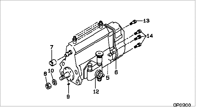
| 000. | [01] | 09200-04370 | PUMP ASSY, INJECTI | 32C6502050 |
| 005. | [01] | 19010-00480 | BODY ASSY, INJECTI | |
| 006. | [01] | 19080-06500 | GOVERNOR ASSY, MEC | |
| 007. | [01] | 09001-80241 | COVER, CONTROL RAC | 09001-80241 |
| 008. | [01] | 94905-02450 | NUT, HEXAGON | 94905-02450 |
| 009. | [01] | 94913-00190 | KEY, WOODRUFF | 94913-00190 |
| 010. | [01] | 94901-50500 | WASHER, SPRING | 94901-50500 |
| 012. | [01] | 09210-01551 | PUMP ASSY, FUEL FE | 34461-09050 |
| 013. | [01] | 91518-08221 | BOLT, W/WASHER | 91518-08221 |
| 014. | [06] | 91418-06161 | BOLT, W/WASHER | 91418-06161 |
Include in #3:
09200-04370
as PUMP ASSY, INJECTI
Cross reference number
| Part num | Firm num | Firm | Name |
| 09200-04370 | 32C6502050 | PUMP ASSY, INJECTI | |
| 32C6502050 | MITSUBISHI | PUMP ASSY, INJECTI |
Information:
Adjust
1. The ejector should operate freely without binding. To adjust the guide rollers, loosen the roller shaft clamping bolt. 2. Turn the roller (eccentric) shaft to position the roller. 3. Tighten the clamping bolt. Clearance between the guide rollers and the scraper bowl should be 3.00 to 20.00 mm (.118 to .787 in).Ejector Carrier Rollers
(631 & 637)
Adjust
1. The ejector should operate freely without dragging. To adjust the carrier rollers, loosen the clamping bolt. 2. Turn the roller (eccentric) shaft to position the roller.3. Tighten the clamping bolt. Clearance between the bottom of the ejector and the bottom of the bowl should be 1.0 to 13.0 mm (.04 to .50 in).Ejector Support Rollers
(631 & 637)
Adjust
1. The ejector should operate freely without dragging. To adjust the carrier rollers, loosen the clamping bolt. 2. Turn the roller (eccentric) shaft to position the roller. 3. Tighten the clamping bolt. The distance between rollers, outside to outside, should be .00 to 6.00 mm (.00 to .236 in) less than the narrowest dimension between the roller guide tracks.Refer to the Service Manual for your machine or contact your Caterpillar dealer for the correct adjustment procedure.Ejector Carriage Rollers
(639)
Adjust
Do not get under the push frame unless the front engine is stopped and the ejector floor is blocked.
1. Install pin in the position that will block movement of the carriage.See "Blocking the Ejector Floor Closed" in the "Safety" section of the Operation (Operator's) Guide. 2. The carriage should operate freely without binding. To adjust the carriage rollers, loosen the roller shaft clamping bolt. 3. Turn the roller (eccentric) shaft to position the rollers. 4. Tighten the clamping bolt. The distance between rollers, outside to outside, should be .00 to 1.50 mm (.00 to .060 in) less than the narrowest dimension between the guide tracks on the push frame.