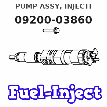
Information pump assy, injecti
Nozzle:
0935004450
Rating:
KIT List:
| Pump assy, fuel fe | 1922900060 |
| Body assy, injecti | 1904400320 |
| Governor assy, mec | 1908900170 |
Components :
| 001. | PUMP ASSY, INJECTI | 09200-03860 |
| 002. | PUMP ASSY, FUEL FE | 09210-03310 |
| 003. | BODY ASSY, INJECTI | 19010-01030 |
| 004. | GOVERNOR ASSY, MEC | 19080-02840 |
Scheme ###:
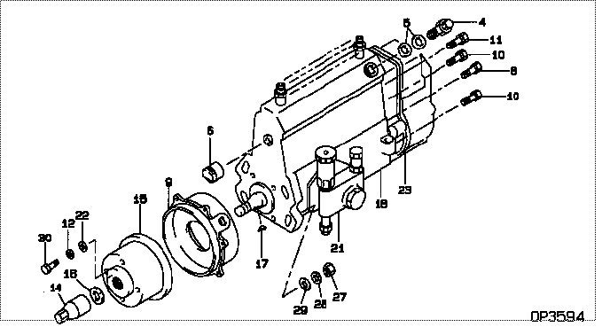
| 000. | [01] | 09200-03860 | PUMP ASSY, INJECTI | 22030-2870 |
| 000. | [01] | 09200-03860 | PUMP ASSY, INJECTI | S2203-02870 |
| 004. | [01] | 09031-00240 | VALVE ASSY, OVERFL | 22107-1290A |
| 005. | [02] | 94901-02480 | WASHER | 22847-1940A |
| 006. | [01] | 09001-80290 | COVER, CONTROL RAC | 22114-1020A |
| 008. | [01] | 91418-06141 | BOLT, W/WASHER | 22815-1480A |
| 009. | [01] | 09006-00150 | COVER SUB-ASSY, TI | 22825-1470A |
| 010. | [05] | 91418-06161 | BOLT, W/WASHER | 22815-1380A |
| 011. | [01] | 91518-08221 | BOLT, W/WASHER | 22815-1190A |
| 012. | [04] | 90258-08001 | WASHER, SPRING | 22877-1720A |
| 014. | [01] | 09001-20220 | NUT, TIMER ROUND | 22511-1060A |
| 015. | [01] | 09255-10420 | BLOCK, COUPLING | 22630-1030A |
| 016. | [01] | 94901-40210 | WASHER, COUNTERSUN | 22867-1320A |
| 017. | [01] | 94913-00210 | KEY, WOODRUFF | 22895-1010A |
| 018. | [01] | 19010-01030 | BODY ASSY, INJECTI | |
| 021. | [01] | 09210-03310 | PUMP ASSY, FUEL FE | |
| 022. | [04] | 09241-70060 | WASHER, COUPLING S | 22867-1490A |
| 023. | [01] | 19080-02840 | GOVERNOR ASSY, MEC | 22330-2180 |
| 027. | [04] | 91266-10081 | NUT, HEXAGON | 22825-1490A |
| 028. | [04] | 90258-10001 | WASHER, SPRING | 28219-1120A |
| 029. | [04] | 94901-15020 | WASHER, STEEL PLAT | 22877-1551A |
| 030. | [04] | 94904-04870 | BOLT, HEXAGON | 22815-2380A |
Include in #3:
09200-03860
as PUMP ASSY, INJECTI
09200-03860
Cross reference number
| Part num | Firm num | Firm | Name |
| 09200-03860 | 22030-2870 | PUMP ASSY, INJECTI | |
| 22030-2870 | HINO | PUMP ASSY, INJECTI | |
| S2203-02870 | HINO | PUMP ASSY, INJECTI |
Information:
1. Remove bolts (1) and the washers that hold rocker shaft assembly (2) in position.2. Remove rocker shaft assembly (2). Remove the O-ring seal from the rear rocker arm support bracket.3. Put identification marks on push rods (3) as to their location in the engine. Remove the push rods.Install Rocker Shaft Assembly & Push Rods
1. Install push rods (1). Make sure they are in their original location in the engine and in position in the valve lifters.
Loosen the adjusting screws on the rocker arms. This will prevent a bent valve or push rod during installation of the rocker shaft assembly.
2. Install a new O-ring seal in the rear rocker arm support bracket. Put 2P2506 Thread Lubricant on all of the bolts that hold the rocker shaft assembly in position except for the bolt that goes through the rear rocker arm support bracket.3. Put rocker shaft assembly (2) in position on the engine. Make sure the dowels in the support bracket are in alignment with the dowel holes in the cylinder head. Make sure the rocker arms are engaged with the push rods.4. Install the bolts and washers that hold the rocker shaft assembly in position. Tighten them until they are finger tight.
3304 Engine Sequence
3306 Engine Sequence5. Tighten the bolts that hold the rocker shaft as follows:a. Tighten the bolts in number sequence to a torque of 156 N m (115 lb ft).b. Tighten the bolts in number sequence to a torque of 250 17 N m (185 13 lb ft).c. Tighten the bolts again in number sequence to a torque of 250 17 N m (185 13 lb ft).6. See "Valve Clearance Setting" in Testing & Adjusting. Make an adjustment to the valves so the intake valves have 0.38 mm (.015 in) clearance and the exhaust valves have 0.64 mm (.025 in) clearance. Tighten the locknuts for the adjusting screws to a torque of 29 7 N m (21 5 lb ft).End By:a. install valve cover