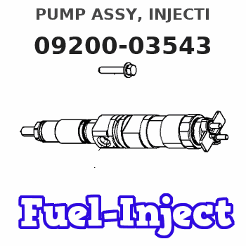
Information pump assy, injecti
Rating:
Scheme ###:

| 000. | [01] | 09200-03543 | PUMP ASSY, INJECTI | 22010-8314 |
| 000. | [01] | 09200-03543 | PUMP ASSY, INJECTI | S2201-08314 |
| 003. | [01] | 19010-01430 | BODY ASSY, INJECTI | 22110-3580A |
| 004. | [01] | 09130-06322 | GOVERNOR ASSY, MEC | 22310-6730A |
| 005. | [01] | 09180-04001 | TIMER ASSY, AUTOMA | S2251-02870-A |
| 006. | [01] | 09001-20340 | NUT, TIMER ROUND | S2282-52240-A |
| 007. | [01] | 09250-01061 | COUPLING ASSY | S2261-01860-A |
| 008. | [01] | 90458-05750 | KEY, WOODRUFF | S2289-11070-A |
| 009. | [01] | 09210-03271 | PUMP ASSY, FUEL FE | S2257-01860-A |
| 010. | [01] | 09001-80381 | COVER, CONTROL RAC | S2211-41200-A |
| 011. | [01] | 94901-81550 | WASHER, COPPER PLA | SL722-02215 |
| 012. | [01] | 94904-76900 | BOLT, W/WASHER | S2281-53230-A |
| 013. | [04] | 94904-76890 | BOLT, W/WASHER | S2281-53210-A |
| 014. | [01] | 94904-76910 | BOLT, W/WASHER | S2281-53240-A |
| 015. | [02] | 94904-76880 | BOLT, W/WASHER | S2281-53320-A |
| 020. | [02] | 09103-10310 | NUT, CAP | S2234-22020-A |
| 021. | [01] | 09031-00450 | VALVE ASSY, OVERFL | S2210-71570-A |
| 022. | [02] | 94901-02480 | WASHER | S2284-71940-A |
| 023. | [01] | 09045-30160 | STAY, INJECTION PU | S1140-91261-A |
| 024. | [02] | 91418-08351 | BOLT, W/WASHER | S2281-53380-A |
| 025. | [01] | 09069-00870 | BRACKET SUB-ASSY, | 22044-1400A |
| 026. | [02] | 91808-08121 | BOLT, FLANGE | S2281-53330-A |
| 027. | [01] | 09028-50030 | CAP | S2232-31210-A |
Include in #3:
09200-03543
as PUMP ASSY, INJECTI
09200-03543
Cross reference number
| Part num | Firm num | Firm | Name |
| 09200-03543 | 22010-8314 | PUMP ASSY, INJECTI |
Information:
3300 Variable Power Supplement
This supplement is to be used for those applications of 3300 Engines in a variable horsepower configuration.
A mechanic that has the proper training is the only one to make the adjustment of low idle and high idle rpm. The correct low idle, high idle rpm and the measurement for adjustment of the fuel settings are in the FUEL SETTING AND RELATED INFORMATION FICHE.
3306 New Scroll Fuel System (NSFS) Hydraulic Actuator
The variable power actuator is mounted to the rear of the governor housing, where the shutoff solenoid is normally mounted. The actuator rod may be in one of two positions -- extended or retracted. The extended position limits the fuel rack travel to the lower power fuel setting. The retracted position allows the fuel rack to travel to the higher power fuel setting. By limiting the travel of the fuel rack, the fuel being injected into the engine is controlled. Fuel being injected into the engine determines the output power of the engine. The position of the actuator rod is determined by the gear engaged in the transmission of the applicable vehicle.High Power Range
Typical Variable Power Arrangement
1. Manifold. 2. Solenoid control valve. 3. Variable power actuator. 4. Governor control lever. 5. Transmission. 6. Switch.An electric switch (6) is mounted in the transmission (5). The transmission (5) is shifted into a gear where the higher power range is allowed. A transmission interlock pin causes the normally open switch (6) to close. When switch (6) is closed, it energizes solenoid control valve (2). The energized solenoid control valve (2) allows engine lube oil (under normal engine lube oil pressure) to flow through manifold (1) and into actuator (3).
Governor And Actuator
3. Actuator. 7. Oil inlet/outlet port. 11. Governor servo valve. 12. Lever. 13. Governor control shaft. 14. Actuator rod.The engine oil coming in port (7) compresses spring (15) and moves actuator rod (14) to the RETRACTED position. The RETRACTED actuator rod (14) allows the fuel rack more travel in the FUEL ON direction by a mechanical linkage through the governor servo valve (11) and lever (12). The fuel rack travel is now limited by the fuel setting screw.The actuator rod (14) will remain in the RETRACTED position as long as solenoid control valve (2) is energized. A light on the operator's console indicates when the engine is operating in the higher power range.
Governor And Variable Power Actuator (Retracted Position7. Oil inlet/outlet port.8. Washered adjusting nut.9. Jam nut.10. Dust cover.11. Governor servo valve.12. Lever.13. Governor control shaft.14. Actuator rod.15. Actuator spring.Low Power Range
Typical Variable Power Arrangement1. Manifold.2. Solenoid control valve.3. Actuator.4. Governor control lever.5. Transmission.6. Switch.The transmission (5) is engaged in a gear where the high power range is NOT allowed. A transmission interlock pin does NOT close the normally open switch (6). The open switch (6) de-energizes the solenoid control valve (2).
Typical Oil Line Arrangement1. Manifold.2. Solenoid control valve.3. Actuator.16. Incoming oil line.17. Oil line.18. Oil return line.The de-energized (closed) solenoid control valve (2) blocks incoming engine oil from