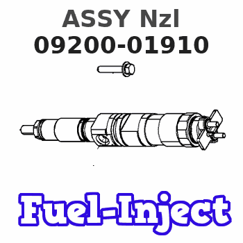
Information assy nzl
Nozzle:
0935002240

Rating:
KIT List:
| Pump assy, fuel fe | 1922900060 |
| Body assy, injecti | 1904400330 |
| Governor assy, mec | 1908900180 |
Components :
| 001. | PUMP ASSY, INJECTI | 09200-01910 |
| 002. | PUMP ASSY, FUEL FE | 09210-02670 |
| 003. | BODY ASSY, INJECTI | 19010-00650 |
| 004. | GOVERNOR ASSY, MEC | 19080-05030 |
Cross reference number
| Part num | Firm num | Firm | Name |
| 09200-01910 | ASSY Nzl | ||
| 22100-78214-71 | TICO | PUMP ASSY, INJECTI |
Information:
View A-A (Rear Face)(6) Bores in block for all camshaft bearings except front bearing ... 69.000 0.038 mm (2.7165 .0015 in)(7) Locate bearing oil hole for all camshaft bearings (except front bearing) at top of bore.
Front Face(8) Bore in block for front camshaft bearing ... 70.000 0.025 mm (2.7559 .0010 in)(9) Front camshaft bearing joint location.(10) Front camshaft bearing oil hole. Install front camshaft bearing with bearing oil hole (10) aligned with oil hole in block and bearing joint (9) positioned as shown.(11) Width of main bearing cap ... 159.995 0.020 mm (6.2990 .0008 in) Width of cylinder block for main bearing cap ... 160.000 0.018 mm (6.2992 .0007 in)(12) Bore in block for main bearings ... 95.000 0.013 mm (3.7402 .0005 in)(13) Main bearing cap bolts. Install as follows: Install bearing caps with sequence number to the right, 1 through 5 (for 4 cylinder) or 1 through 7 (for 6 cylinder), front to rear.a. Before assembly, put 2P2506 Thread Lubricant on the bolt threads and washer face.b. Tighten both bolts of each bearing cap to a torque of ... 54 7 N m (40 5 lb ft)c. Then tighten bolts an additional ... 90 5 degrees (1/4 turn)(14) Location of bearing cap sequence number.(15) Dimension from centerline of crankshaft bore to pan rail ... 110.00 mm (4.331 in)(16) Dimension from centerline of crankshaft bore to top of block ... 322.00 .017 mm (12.677 .0007 in)(17) Cylinder bore size ... 105.025 .025 mm (4.1348 .0010 in) Bore size must be checked with a 4C4377 Cylinder Head Stress Plate and gasket installed. Refer to Installation Of 7C6208 Cylinder Sleeve, Special Instruction Form No. SEHS9047. (18) Piston cooling jet. Check piston cooling jets by inserting a 1.3 mm (.05 in) diameter drill rod into jet. Rod must pass through a 5.0 mm (.20 in) diameter circle in location (A) and a 13 mm (.51 in) diameter circle in location (B). Dimension (C) is 25.9 mm (1.02 in). Dimension (D) is 33.4 mm (1.31 in). Dimension (E) is 26.95 mm (1.061 in). Dimension (F) is 9.8 mm (.39 in). Dimension (G) is 50 mm (2.0 in). Distance four sleeves (19) extend from side face ... 5.0 0.5 mm (.20 .02 in)