Information pump assy, injecti
Nozzle:
0935005880
Rating:
KIT List:
| Pump assy, fuel fe | 1922900060 |
| Body assy, injecti | 1904400320 |
| Governor assy, mec | 1908900170 |
Components :
| 001. | PUMP ASSY, INJECTI | 09200-01900 |
| 002. | PUMP ASSY, FUEL FE | 09210-01291 |
| 003. | BODY ASSY, INJECTI | 19010-00900 |
| 004. | GOVERNOR ASSY, MEC | 19080-05010 |
Scheme ###:
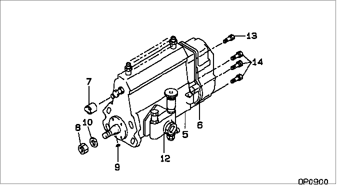
| 000. | [01] | 09200-01900 | PUMP ASSY, INJECTI | 32A6514520 |
| 005. | [01] | 19010-00901 | BODY ASSY, INJECTI | |
| 006. | [01] | 19080-05010 | GOVERNOR ASSY, MEC | |
| 007. | [01] | 09001-80081 | COVER, CONTROL RAC | 09001-80081 |
| 008. | [01] | 94905-03570 | NUT, HEXAGON | |
| 009. | [01] | 94913-00300 | KEY, WOODRUFF | |
| 010. | [01] | 94901-50590 | WASHER, SPRING | |
| 012. | [01] | 09210-01291 | PUMP ASSY, FUEL FE | 34461-09060 |
| 013. | [01] | 91518-08221 | BOLT, W/WASHER | 91518-08221 |
| 014. | [06] | 91418-06161 | BOLT, W/WASHER | 91418-06161 |
Include in #3:
09200-01900
as PUMP ASSY, INJECTI
Cross reference number
| Part num | Firm num | Firm | Name |
| 09200-01900 | 32A6514520 | PUMP ASSY, INJECTI | |
| 32A6514520 | MITSUBISHI | PUMP ASSY, INJECTI |
Information:
Flow of coolantWater Pump
Removal and Inspection
Removal sequence and points to check on water pump(1) Cooling fan(2) Fan spacer(3) Water pump pulley(4) Fan belt(5) Water bypass hose(6) Water pump assembly Key Points for RemovalRemoval of the water pump pulley and fa belt is possible after loosening slightly both the adjusting bolt (1) and support bolt (2). This allows the alternator to be moved and then the V-belt slackened.
Removing water pump pulley Key Points for InspectionTurn the pump by hand to check the impeller shaft for smooth and quiet rotation. If irregular or noisy rotation is detected, replace them as an assembly.
Inspecting impeller and shaft rotationInstallation
Perform installation by following the removal sequence in reverse: Key Points for Inspection(1) Install the six water pump mounting bolts in their correct locations by referring to the figure on the right for the nominal diameters and lengths from bottom of head.
Correct locations of water pump mounting bolts(2) Use a new gasket when installing the water pump.(3) Adjust the fan belt tension according to the following specification.Unit: mm (in.)
Fan belt tension adjustmentThermostat
Disassembly
Removal sequence and points to check on the thermostat(1) Water hose(2) Water outlet fitting(3) Thermostat(4) Thermostat fitting(5) Thermo switchInspection
Key Points for Removal(1) Operation Test of Thermostat
Put the thermostat in a container of water. Heat the water and record both of the temperatures at which the valve starts to open and at which the valve lift reaches 8 mm (0.3 in.). If the readings do not conform to the specification below, replace the thermostat.
Operation test of thermostat
Carry out this operation with extreme care to avoid burns and prevent fire.
Installation
Except that the instructions shown below are to be followed, perform installation by following the removal sequence in reverse: Key Points for Inspection(1) Thermo Switch
Apply sealant to the threads an tighten to the specified torque.
Installing thermo switch(1) Thermostat
Make sure that the thermostat flange fits correctly into the counterbore in the thermostat fitting.
Installing thermostat