Information timer assy, automa
Rating:
KIT List:
| Timer assy, automa | No Application |
| Timer assy, automa | No Application |
| Timer assy, automa | No Application |
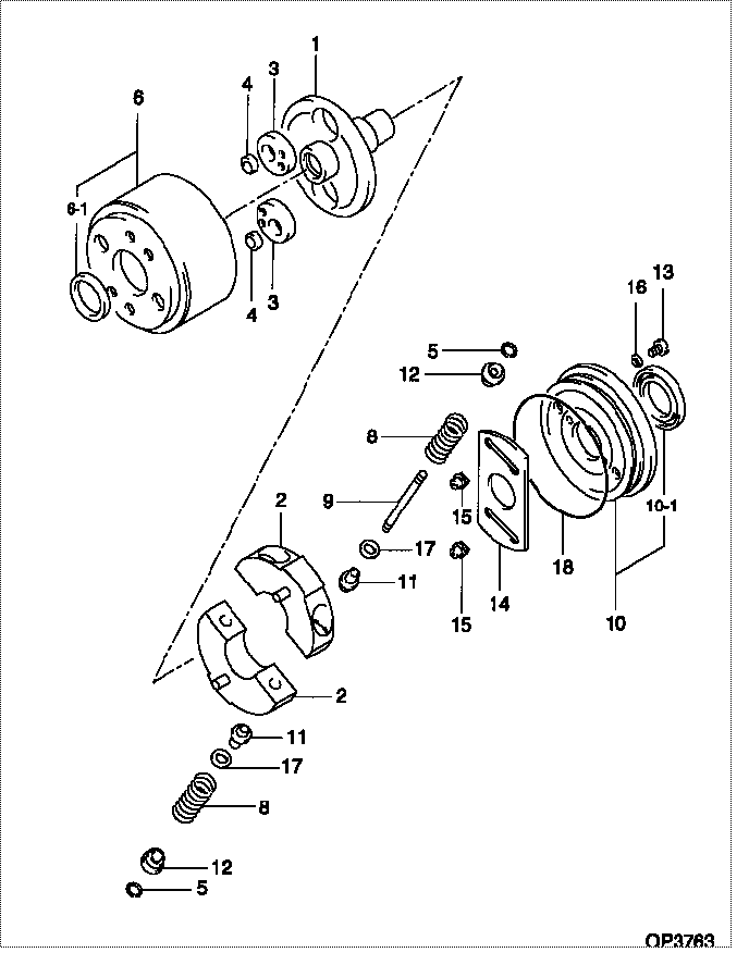
Scheme ###:
| 000. | [01] | 09180-03690 | TIMER ASSY, AUTOMA | 22510-2760 |
| 000. | [01] | 09180-03690 | TIMER ASSY, AUTOMA | S2251-02760 |
| 001. | [01] | 09181-11890 | HUB, TIMER | 22516-1980A |
| 002. | [02] | 09183-61100 | WEIGHT SUB-ASSY, T | 22514-3740A |
| 003. | [02] | 09189-50250 | CAM, TIMER | 22545-1340A |
| 004. | [02] | 09189-50260 | CAM, TIMER | 22545-1350A |
| 005. | [04] | 94907-10880 | WASHER, SNAP | 22518-1110A |
| 006. | [01] | 09184-01170 | FLANGE, TIMER DRIV | 22513-2500A |
| 006-001. | [01] | 94915-02910 | SEAL, OIL | 22827-1680A |
| 008. | [4C] | 09181-81300 | SPRING, TIMER SUB | |
| 008. | [4C] | 09181-81330 | SPRING, TIMER SUB | 22515-6090A |
| 009. | [02] | 09188-40140 | SUPPORT, TIMER SPR | 22517-1590A |
| 010. | [01] | 09187-00240 | COVER SUB-ASSY, TI | |
| 010. | [01] | 09187-00190 | COVER SUB-ASSY, TI | 22501-1210A |
| 010-001. | [01] | 94915-02920 | SEAL, OIL | 22827-1690A |
| 011. | [04] | 09181-70290 | SEAT | 22517-1360A |
| 012. | [04] | 09181-70440 | SEAT | 22517-1770A |
| 013. | [02] | 09186-20010 | SCREW, TIMER HUB | 22865-1270A |
| 014. | [01] | 09186-70240 | PLATE, TIMER DRIVI | 22513-2110A |
| 015. | [02] | 09188-20030 | ROLLER, TIMER | 22522-1040A |
| 016. | [02] | 94901-81020 | WASHER, COPPER PLA | 22847-1300A |
| 017. | [8C] | 94901-38180 | WASHER, PLATE, SK | 22885-5870A |
| 017. | [8C] | 94901-38190 | WASHER, PLATE, SK | 22885-5880A |
| 017. | [8C] | 94901-38200 | WASHER, PLATE, SK | 22885-5890A |
| 017. | [8C] | 94901-38910 | WASHER, PLATE, SK | 22885-7340A |
| 017. | [8C] | 94901-38920 | WASHER, PLATE, SK | 22885-7350A |
| 018. | [01] | 94914-03950 | O-RING | 22817-1930A |
Include in #3:
Cross reference number
| Part num | Firm num | Firm | Name |
| 09180-03690 | 22510-2760 | TIMER ASSY, AUTOMA | |
| 22510-2760A | HINO | TIMER ASSY, AUTOMA | |
| 22510-2760 | HINO | TIMER ASSY, AUTOMA | |
| S2251-02760 | HINO | TIMER ASSY, AUTOMA |
Information:
Grounding Practices
Proper grounding for the vessel's electrical system and the engine electrical system is necessary for proper performance and reliability. Improper grounding will result in unreliable electrical circuit paths and in uncontrolled electrical circuit paths.Uncontrolled engine electrical circuit paths can result in damage to the main bearings, to the crankshaft bearing journal surfaces, and to the aluminum components.Uncontrolled electrical circuit paths can cause electrical noise which may degrade the vessel's performance and the radio performance.In order to ensure proper functioning of the vessel's electrical system and of the engine electrical system, an engine-to-frame ground strap with a direct path to the battery must be used. This is provided by a ground from the electric starting motor to the frame and to the negative battery post.The ground path must be capable of carrying any potential currents. A wire that is AWG 0 or more is recommended for the ground of the electric starting motor.The engine alternator should be grounded to the battery with a wire size that is capable of managing the full charging current of the alternator.
When jump starting an engine, the instructions in the Operation and Maintenance Manual, "Starting with Jump Start Cables" should be followed in order to properly start the engine.This engine may be equipped with a 12 volt starting system or with a 24 volt starting system. Only equal voltage for boost starting should be used. The use of a welder or of a higher voltage will damage the electrical system.
The engine has several input components which are electronic. These components require an operating voltage.This engine is tolerant of common external sources of electrical noise. Electromechanical buzzers can cause disruptions in the power supply. If electromechanical buzzers are used on the vessel, the engine electronics should be powered directly from the battery system through a dedicated relay. The engine electronics should not be powered through a common power bus with other devices that are activated by the keyswitch.Engine Electrical System
The electrical system can have three separate circuits. The three circuits are the charging circuit, the starting circuit, and the low amperage circuit. Some of the electrical system components are used in more than one circuit.The charging circuit is in operation when the engine is running. The charging circuit uses an alternator in order to create electricity. A voltage regulator in the circuit controls the electrical output in order to maintain the battery at full charge.The starting circuit is in operation when the start switch is activated.The low amperage circuit and the charging circuit are connected through the ammeter. The starting circuit is not connected through the ammeter.Starting System Components
Solenoid
Illustration 1 g00292316
Typical cross section of a solenoidA solenoid is an electromagnetic switch that performs two basic functions:
The solenoid closes the high current circuit for the electric starting motor with a low current start switch circuit.
The solenoid engages the pinion for the electric starting motor with the ring gear.The solenoid has windings (one set or two sets) around a hollow cylinder. A plunger with a spring load