Information timer assy, automa

Rating:
KIT List:
| Timer assy, automa | No Application |
| Timer assy, automa | No Application |
Scheme ###:
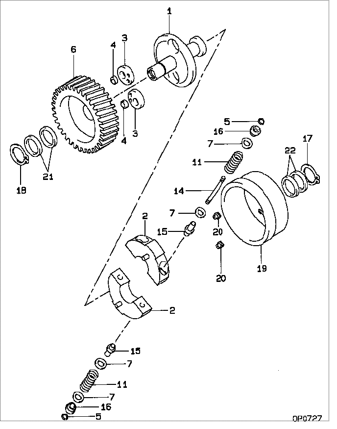
| 000. | [01] | 09180-03680 | TIMER ASSY, AUTOMA | ME736796 |
| 001. | [01] | 09181-11820 | HUB, TIMER | ME736549 |
| 002. | [02] | 09183-61090 | WEIGHT SUB-ASSY, T | ME736811 |
| 003. | [02] | 09189-50340 | CAM, TIMER | ME736494 |
| 004. | [02] | 09189-50330 | CAM, TIMER | ME736495 |
| 005. | [04] | 94907-10880 | WASHER, SNAP | ME703750 |
| 006. | [01] | 09185-00390 | GEAR, DRIVE | ME736089 |
| 007. | [8C] | 94901-39080 | WASHER, PLATE, SK | ME736095 |
| 007. | [8C] | 94901-39070 | WASHER, PLATE, SK | ME736094 |
| 007. | [8C] | 94901-39060 | WASHER, PLATE, SK | ME736093 |
| 007. | [8C] | 94901-39050 | WASHER, PLATE, SK | ME736092 |
| 007. | [8C] | 94901-39040 | WASHER, PLATE, SK | ME736091 |
| 007. | [8C] | 94901-39030 | WASHER, PLATE, SK | ME736090 |
| 011. | [04] | 09181-81240 | SPRING, TIMER SUB | ME736812 |
| 014. | [02] | 09188-40130 | SUPPORT, TIMER SPR | ME736098 |
| 015. | [04] | 09181-70400 | SEAT | ME736100 |
| 016. | [04] | 09181-70440 | SEAT | ME736496 |
| 017. | [01] | 90557-45000 | RING, SHAFT SNAP | ME736101 |
| 018. | [01] | 90557-35000 | RING, SHAFT SNAP | ME703758 |
| 019. | [01] | 09185-60461 | COVER, TIMER | ME736102 |
| 020. | [02] | 09188-20070 | ROLLER, TIMER | ME736802 |
| 021. | [2C] | 94901-38070 | WASHER, PLATE, SK | ME703767 |
| 021. | [2C] | 94901-38060 | WASHER, PLATE, SK | ME703766 |
| 021. | [2C] | 94901-38050 | WASHER, PLATE, SK | ME703765 |
| 021. | [2C] | 94901-38040 | WASHER, PLATE, SK | ME703764 |
| 021. | [2C] | 94901-38030 | WASHER, PLATE, SK | ME703763 |
| 021. | [2C] | 94901-38020 | WASHER, PLATE, SK | ME703762 |
| 022. | [2C] | 94901-38970 | WASHER, PLATE, SK | ME736103 |
| 022. | [2C] | 94901-38980 | WASHER, PLATE, SK | ME736104 |
| 022. | [2C] | 94901-38990 | WASHER, PLATE, SK | ME736105 |
| 022. | [2C] | 94901-39000 | WASHER, PLATE, SK | ME736106 |
| 022. | [2C] | 94901-39010 | WASHER, PLATE, SK | ME736107 |
| 022. | [2C] | 94901-39020 | WASHER, PLATE, SK | ME736108 |
Include in #3:
09180-03680
as TIMER ASSY, AUTOMA
Cross reference number
| Part num | Firm num | Firm | Name |
| 09180-03680 | ME736796 | TIMER ASSY, AUTOMA | |
| ME736796 | MITSUBISHI | TIMER ASSY, AUTOMA |
Information:
Introduction
The problem that is identified below has a known solution. Use the solution that is identified below.Problem
Incorrect wiring on heated diesel exhaust fluid (DEF) lines may reduce thawing performance in colder climates on the machines listed above. Incorrect wiring may also cause the following codes:
E1309Low Aftertreatment #1 SCR Catalyst Conversion Efficiency
3821-7Aftertreatment #1 Diesel Exhause Fluid Dosing Calve Actuator: Not Responding Properly
E1370Aftertreatment #1 Diesel Exhaust Fluid Dosing Unit Loss of Prime
E1389Aftertreatment #1 SCR Operator InducementSolution
Do not operate or work on this product unless you have read and understood the instruction and warnings in the relevant Operation and Maintenance Manuals and relevant service literature. Failure to follow the instructions or heed the warnings could result in injury or death. Proper care is your responsibility.
Table 1
Required Parts
Qty Part Number Part Name
2 3S-2093 Cable Strap
Table 2
Required Pin Changes for 374-8331 Connector Plug As
Circuit Wire Color New Pin Location Former Pin Location
U940 Gray 23 15
U941 Pink 24 16
U942 Green 39 23
U937 White 73 24
U938 Blue 15 39
U939 Orange 16 73 Procedure to Change Connector Plug Assembly Pins
Turn the engine disconnect switch to the OFF position.
Illustration 1 g06613177
Back of ECM
(A) Center allen head screw
Locate the ECM connector and loosen the center allen head screw (A).
Illustration 2 g06613182
ECM connector removed from ECM
Disengage the ECM connector from the ECM.
Illustration 3 g06613186
Area to mark with paint
(B) Gray locking wedge
(D) Connector cover
Paint a mark on the gray locking wedge (B) and the connector to ensure correct orientation when reassembled.Note: Paint assists identification of pin positions when removing and relocating wire circuits.
Illustration 4 g06613187
View of back of Connector cover (D)
( C) Cable straps
(D) Connector cover
Illustration 5 g06613189
Connector cover (D) removed
Cut cable straps (C) securing the harness wires to the connector cover (D).Remove connector cover (D).
Illustration 6 g06613192
Gray locking wedge removed from ECM connector
Remove gray locking wedge from 86-pin connector to provide access to release the DT Pins.Note: Circuit U937 to be removed from pin location number 24 and transferred to pin location 73.Note: Cloth tape will need to be removed to the split in the harness main bundle.Note: The U937 wire can then be routed into the opposite branch to gain enough free length to make the connection.Note: The U939 wire removed from pin location 73 has adequate length to be loaded into location 16.
Transfer and relocate the wires as detailed in Table 2.
Reinstall the locking wedge (B) when all wires have been transferred and relocated.
Illustration 7 g06613197
View of back of ECM connector with connector cover (D) removed
Apply cloth tape to both wire branches from the main bundle of wires up the branches to the harness strain relief strap location.