Information timer assy, automa
Rating:
Scheme ###:
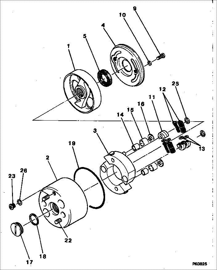
| 000. | [01] | 09180-01021 | TIMER ASSY, AUTOMA | 22510-1120 |
| 001. | [01] | 09181-00222 | HUB ASSY, TIMER | 22516-1360A |
| 002. | [01] | 09184-00221 | FLANGE, TIMER DRIV | 22513-1430A |
| 003. | [02] | 09183-60171 | WEIGHT SUB-ASSY, T | |
| 004. | [01] | 09185-60310 | COVER, TIMER | 22512-1010A |
| 005. | [01] | 94915-00980 | SEAL, OIL | 22827-1080A |
| 009. | [02] | 90128-08141 | BOLT, HEXAGON | |
| 010. | [02] | 09022-20080 | WASHER, FUEL PIPE | 22847-1330A |
| 011. | [04] | 09188-40011 | SUPPORT, TIMER SPR | 22517-1110A |
| 012. | [04] | 09181-90900 | SPRING, TIMER | |
| 013. | [4C] | 94901-34210 | WASHER, PLATE, SK | 22885-1690A |
| 013. | [4C] | 94901-34200 | WASHER, PLATE, SK | 22885-1680A |
| 013. | [4C] | 94901-34190 | WASHER, PLATE, SK | 22885-1670A |
| 013. | [4C] | 94901-34180 | WASHER, PLATE, SK | 22885-1660A |
| 013. | [4C] | 94901-34170 | WASHER, PLATE, SK | 22885-1650A |
| 014. | [02] | 09188-30010 | BUSHING, TIMER ROL | 22521-1020 |
| 015. | [02] | 09188-20010 | ROLLER, TIMER | 22522-1010A |
| 016. | [02] | 94901-15070 | WASHER, STEEL PLAT | 22867-1120A |
| 017. | [01] | 09188-50020 | SCREW, TIMER OIL S | 22845-1120A |
| 018. | [01] | 09083-90040 | PACKING | 22847-2410A |
| 018. | [01] | 09083-90020 | PACKING | 22847-1190A |
| 019. | [01] | 94914-01560 | O-RING | 22817-1150A |
| 022. | [01] | 94904-30440 | BOLT, STUD | 22857-1030A |
| 023. | [01] | 09031-70060 | PLUG, SCREW | 22845-1060A |
| 025. | [02] | 94901-20870 | WASHER, CAP | 22867-1130A |
| 026. | [01] | 94901-81500 | WASHER, COPPER PLA | 22847-1120A |
Include in #3:
09180-01021
as TIMER ASSY, AUTOMA
Cross reference number
| Part num | Firm num | Firm | Name |
| 09180-01021 | 22510-1120 | TIMER ASSY, AUTOMA |
Information:
General Information
For current engines, the first two characters of the serial number stand for the engine family and type. LD stands for a naturally aspirated 4.236 Engine. LH stands for a compensated (turbocharged) 4.236 Engine. The next five characters are the parts list number. These five characters are represented by dashes "-" in this module. The next single letter is the country of origin. The next set of numbers is the production serial number, and the last letter is the year of manufacture.Engine Design
Type ... Four Cylinder, Four StrokeCombustion System ... Direct InjectionNominal Bore ... 98.43 mm (3.875 in)Stroke ... 127 mm (5 in)Cubic Capacity ... 3.86 liters (236 cu in)Compression Ratio 4.236 Engines ... 18 to 1C4.236 Engines ... 16 to 1Number and Arrangement of Cylinders (as seen from front of engine) ... 1-2-3-4Firing Order ... 1-3-4-2Rotation of crankshaft (as seen from front of engine) ... ClockwiseRotation of crankshaft (as seen from front of engine) ... ClockwiseThe left side and right side of engine are as seen from flywheel end. No. 1 cylinder is the front cylinder of the engine.Engine Serial Numbers
Engine Serial Number LocationThe engine serial number is located on the left hand side of the block above the fuel injection pump.For current engines, the first two characters of the serial number stand for the engine family and type. LD stands for a naturally aspirated 4.236 Engine. LH stands for a compensated (turbocharged) 4.236 Engine. The next five characters are the parts list number. The next single letter is the country of origin. The next set of numbers is the production serial number, and the last letter is the year of manufacture. Some new components and improvements have introduced on the 4.236 engine. If there is a difference in service or specifications, it is noted in this module. Engine numbers beginning with LD70179, LD70200, LD70201, LH70189, LH70202 or LH70213 will have the new components and improvements at first production. On 416 Backhoe Loader Engines (engine numbers beginning with LD70178), the engine cut-in serial numbers are given for the changes if available. Following are the numbers that are used in the Backhoe Loaders:LD70178, LD70200 (metric interfacing ... 416 with 4.236 engineLD70179, LD70201 (metric interfacing) ... 426 and 428 with 4.236 engineLH70189, LH70202 (metric interfacing) ... 416, 426 and 428 with C4.236 engineLH70213 (metric interfacing) ... 436 and 438 with 4.236 engineFuel System
Basic Fuel System Diagram
(1) Fuel injectors (atomisers). (2) Fuel return line from injectors. (3) Fuel filter. (4) Fuel return line to tank. (5) Tee. (6) Fuel return line from fuel injection pump. (7) Fuel supply line to injection pump. (8) Fuel lift pump. (9) Water separator. (10) Fuel injection pump. (11) High pressure fuel lines. (12) Fuel tank.When the engine is turning, fuel is pulled from fuel tank (12) through water separator (9) by