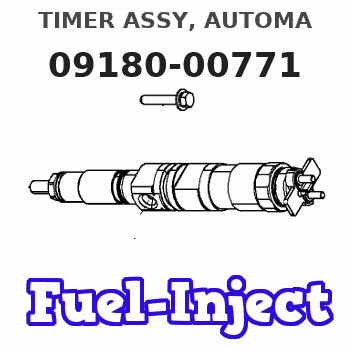
Information timer assy, automa
Rating:
Scheme ###:
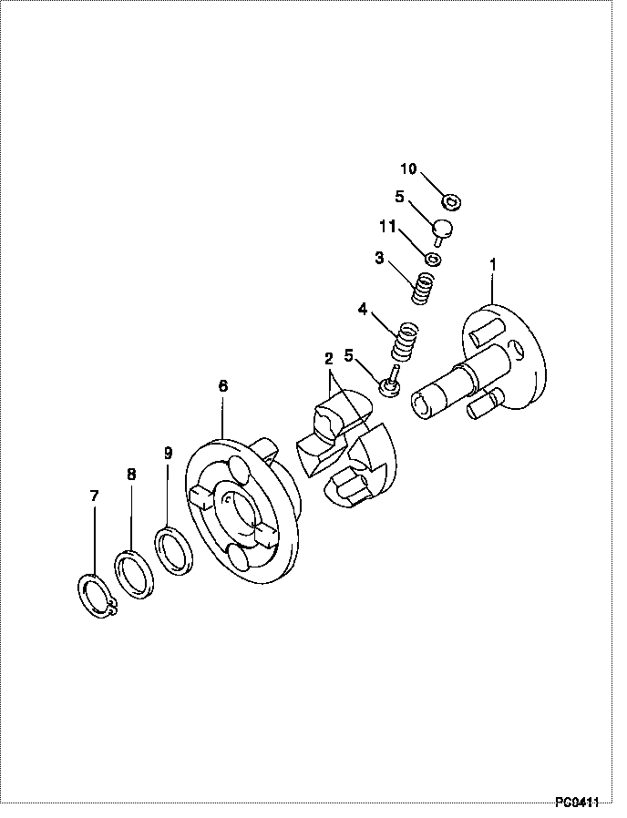
| 000. | [01] | 09180-00771 | TIMER ASSY, AUTOMA | |
| 001. | [01] | 09181-00422 | HUB ASSY, TIMER | |
| 002. | [02] | 09183-60136 | WEIGHT SUB-ASSY, T | ME702212 |
| 003. | [02] | 09181-90640 | SPRING, TIMER | |
| 004. | [02] | 09181-90630 | SPRING, TIMER | |
| 005. | [04] | 09181-70060 | SEAT | |
| 006. | [01] | 09184-00440 | FLANGE, TIMER DRIV | ME703554 |
| 007. | [01] | 90557-28000 | RING, SHAFT SNAP | ME702214 |
| 008. | [01] | 94901-32770 | WASHER, PLATE, SK | ME702216 |
| 009. | [1C] | 94901-32760 | WASHER, PLATE, SK | ME022266 |
| 009. | [1C] | 94901-32950 | WASHER, PLATE, SK | ME022268 |
| 010. | [2C] | 94901-31480 | WASHER, PLATE, SK | ME702215 |
| 010. | [2C] | 94901-31490 | WASHER, PLATE, SK | ME703553 |
| 010. | [2C] | 94901-31850 | WASHER, PLATE, SK | |
| 011. | [2C] | 94901-31390 | WASHER, PLATE, SK | ME703126 |
| 011. | [2C] | 94901-31420 | WASHER, PLATE, SK | ME703279 |
Include in #3:
Cross reference number
| Part num | Firm num | Firm | Name |
| 09180-00771 | TIMER ASSY, AUTOMA |
Information:
In this manual, specifications, service standards, adjustment procedures, disassembly procedures, inspection procedures, and reassembly procedures for the engine are shown in groups. The contents of each group are listed in the index and at the beginning of that group.For instructions on operation and periodic inspection, refer to the operation manual. For instructions on ordering replacement parts, refer to the parts catalog. For information on the engine's structure and function, refer to relevant training material.1. Items Shown in This Manual(1) Parts mentioned in the text and shown in the exploded views are numbered in their disassembly sequences.(2) Inspections to be performed during disassembly are shown in in the exploded views.(3) Service standards for inspection and repair operations are indicated at relevant places in the text and in a table in Group 2.(4) The sequences in which parts should be reassembled during reassembly operations are shown under reassembly drawings in this manner: .(5) The symbols and headings shown below are used in this manual to highlight particularly important and safety-critical instructions.
Indicates a condition that will cause death or serious injury if incorrect action is taken.
Indicates a condition that may cause death or serious injury if incorrect action is taken.
Indicates a condition that will cause engine damage or slight or moderate injury if incorrect action is taken.
Indicates a supplementary explanation or other important point.(6) With regard to tightening torques, points to which engine oil must be applied are labeled "Wet". Where there is no such indication, parts should be tightened in a dry condition.2. TerminologyTerms used in this manual are defined as follows:(1) Front and RearThe term "front" refers to the fan side of the engine, and the term "rear" applies to the flywheel side.(2) Left and RightThe terms "left" and "right" apply to the sides of the engine as seen from the flywheel.(3) Service Standards* Standard ValueThis term indicates a designed nominal dimension, the designed dimension of a single part, the standard clearance between two parts after assembly, or a standard performance value for an assembly.* LimitThis term indicates a value beyond which a part is no longer useable in terms of performance and strength and must be repaired or replaced.