Information governor assy, mec
Rating:
Scheme ###:
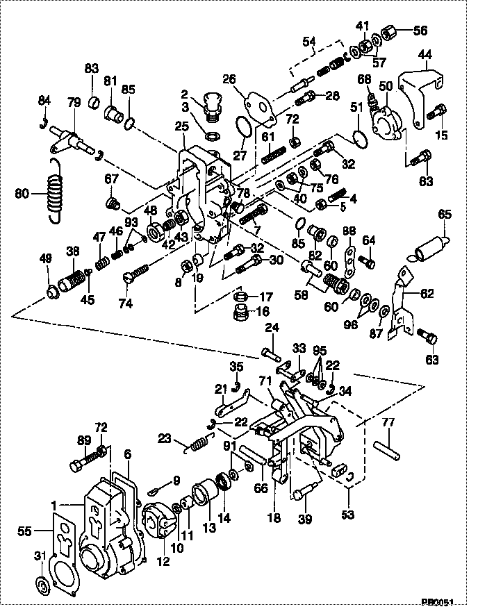
| 000. | [01] | 09080-03470 | GOVERNOR ASSY, MEC | 22310-1630 |
| 001. | [01] | 09081-00102 | HOUSING SUB-ASSY, | 6 306 1310 90 |
| 002. | [01] | 09083-00030 | BREATHER ASSY, MEC | 6 303 1303 41 |
| 003. | [01] | 94901-81040 | WASHER, COPPER PLA | 22867-1170A |
| 004. | [01] | 09152-40081 | SCREW, STOPPER | 22395-1260A |
| 005. | [01] | 94805-30130 | NUT, HEXAGON, W/HO | 22825-1060A |
| 006. | [01] | 09082-30141 | GASKET | 22847-1800A |
| 006. | [01] | 09082-30400 | GASKET | 22847-2390A |
| 007. | [01] | 09128-40080 | SCREW, ADJUSTING | 22395-1470A |
| 008. | [01] | 09634-20010 | NUT, LOCK | 22821-1530A |
| 009. | [01] | 94913-00050 | KEY, WOODRUFF | 22891-1040A |
| 010. | [01] | 94901-50500 | WASHER, SPRING | 22877-1540A |
| 011. | [01] | 09084-40010 | NUT, ROUND | 22353-1070A |
| 012. | [01] | 09084-00101 | FLYWEIGHT ASSY | 6 303 1304 50 |
| 013. | [01] | 09086-10010 | SLEEVE, GOVERNOR | 22305-1110A |
| 014. | [01] | 94910-00010 | BEARING, BALL | 22837-1120A |
| 015. | [01] | 94904-04060 | BOLT, HEXAGON | 6 306 1337 20 |
| 016. | [01] | 09116-70031 | PLUG, SCREW | 22845-1320A |
| 017. | [01] | 09022-20060 | WASHER, FUEL PIPE | 6 366 1331 10 |
| 018. | [01] | 09095-90090 | LEVER ASSY, GUIDE | 22307-1550 |
| 019. | [01] | 09104-90120 | COLLAR | 22332-1040 |
| 021. | [01] | 09097-00090 | SHACKLE ASSY | 22409-1020 |
| 022. | [03] | 90577-05000 | E-RING | 22887-1170A |
| 023. | [01] | 09099-30160 | SPRING, START | 6 306 1333 30 |
| 024. | [01] | 09098-30120 | PIN, CONNECTING | 22338-1030 |
| 025. | [01] | 09101-10702 | COVER, GOVERNOR | 6 306 1313 40 |
| 026. | [01] | 09105-10200 | PLATE, COVER | 22386-1240A |
| 027. | [01] | 94914-02030 | O-RING | 22817-1310A |
| 031. | [01] | 94915-00030 | SEAL, OIL | 22827-1290A |
| 032. | [02] | 94904-50130 | BOLT, HEXAGON, W/ | 6 306 1337 70 |
| 033. | [01] | 09094-00080 | LEVER SUB-ASSY, CO | 22309-1620 |
| 034. | [01] | 09098-30130 | PIN, CONNECTING | 6 306 1314 30 |
| 035. | [01] | 90577-07000 | E-RING | 22887-1240A |
| 038. | [01] | 09091-10111 | SCREW, ADPTER | 22385-1410 |
| 039. | [01] | 09091-90160 | ADAPTER | 22385-1390 |
| 040. | [02] | 09025-10010 | WASHER, INJECTION | 22865-1290A |
| 041. | [01] | 94805-30090 | NUT, HEXAGON, W/HO | 22825-1270A |
| 042. | [01] | 09091-10120 | SCREW, ADPTER | 6 306 1314 50 |
| 043. | [01] | 94905-02460 | NUT, HEXAGON | 22825-1240A |
| 045. | [01] | 09091-70031 | SEAT, SPRING | 22351-1310 |
| 046. | [01] | 09091-80880 | SPRING, MECHANICAL | 22411-1050A |
| 047. | [01] | 09091-81040 | SPRING, MECHANICAL | 22411-1060A |
| 048. | [01] | 09092-30011 | NUT, ADAPTER LOCK | 22825-2090A |
| 049. | [01] | 09104-90081 | COLLAR | 6 306 1315 50 |
| 050. | [01] | 09105-00130 | PLATE SUB-ASSY, CO | 6 306 1315 60 |
| 051. | [01] | 94914-01900 | O-RING | 22817-1550A |
| 053. | [01] | 09092-00021 | LEVER KIT, CONTROL | 6 306 1332 40 |
| 054. | [01] | 09091-00421 | ADAPTER ASSY | 22404-1480A |
| 056. | [01] | 09003-20040 | CAP | 22342-1110A |
| 057. | [02] | 94901-80350 | WASHER, COPPER PLA | 22847-1950A |
| 058. | [01] | 09102-60010 | SHAFT & BUSHING KI | 22420-1010A |
| 060. | [02] | 94915-01150 | SEAL, OIL | 22827-1150A |
| 061. | [01] | 09082-10010 | STOPPER | 22395-1290A |
| 062. | [01] | 09107-00490 | LEVER SUB-ASSY, AD | 22319-1300 |
| 065. | [02] | 09104-10010 | SPRING SUB-ASSY, R | 22341-1590 |
| 066. | [01] | 09098-90020 | SHAFT, LEVER SUPPO | 22338-1060A |
| 067. | [01] | 09099-10010 | PLUG, SCREW | 22845-1210A |
| 068. | [01] | 09106-00020 | GAUGE SUB-ASSY, GO | 6 056 1326 10 |
| 071. | [01] | 09094-00130 | LEVER SUB-ASSY, CO | 22307-1560 |
| 072. | [02] | 94905-30051 | NUT, HEXAGON, W/ H | 22821-1540A |
| 074. | [01] | 09100-60070 | SCREW, STROKE ADJU | 22396-1170A |
| 075. | [01] | 94905-03060 | NUT, HEXAGON | 22825-1260A |
| 076. | [01] | 09003-20080 | CAP | 22342-1180A |
| 077. | [01] | 09103-50183 | SHAFT, MECHANICAL | 22318-1020A |
| 078. | [02] | 09101-60172 | BUSHING, BEARING | 22837-1070 |
| 079. | [01] | 09104-80072 | LEVER SUB-ASSY, SU | 22306-1180 |
| 080. | [01] | 09099-20360 | SPRING, SPEED CONT | 22321-1030 |
| 081. | [01] | 09089-20011 | BUSHING, LEVER | 22322-1440A |
| 082. | [01] | 09089-20040 | BUSHING, LEVER | 22322-1590A |
| 083. | [01] | 09109-40010 | CAP, LEVER | 22855-1060A |
| 084. | [02] | 94907-10090 | WASHER, SNAP | 22887-1050A |
| 085. | [02] | 94914-00080 | O-RING | 22817-1190A |
| 087. | [02] | 09154-60010 | SHIM | 22885-1800A |
| 088. | [01] | 09107-10940 | LEVER, ADJUSTING | 22415-1400A |
| 089. | [01] | 09082-10070 | STOPPER | 22395-1670A |
| 091. | [1C] | 94901-34100 | WASHER, PLATE, SK | 22885-5160A |
| 091. | [1C] | 94901-34090 | WASHER, PLATE, SK | 22885-5150A |
| 091. | [1C] | 94901-34080 | WASHER, PLATE, SK | 22885-5140A |
| 091. | [1C] | 94901-34070 | WASHER, PLATE, SK | 22885-5130A |
| 091. | [1C] | 94901-34060 | WASHER, PLATE, SK | 22885-5120A |
| 093. | [1C] | 94901-33910 | WASHER, PLATE, SK | 6 303 1301 80 |
| 093. | [1C] | 94901-33920 | WASHER, PLATE, SK | 6 306 1319 00 |
| 095. | [03] | 94901-33970 | WASHER, PLATE, SK | 22885-1740A |
| 096. | [2C] | 09154-60080 | SHIM | 22885-1700A |
| 096. | [2C] | 09154-60050 | SHIM | 22885-5110A |
| 096. | [2C] | 09154-60040 | SHIM | 22885-5100A |
| 096. | [2C] | 09154-60030 | SHIM | 22885-5090A |
| 097. | [01] | 94904-04300 | BOLT, HEXAGON | 22815-1630A |
| 098. | [06] | 94904-70620 | BOLT, W/WASHER | 22815-1620A |
Include in #3:
09000-08063
as GOVERNOR ASSY, MEC
09080-03470
Cross reference number
| Part num | Firm num | Firm | Name |
| 09080-03470 | 22310-1630 | GOVERNOR ASSY, MEC | |
| 22310-1630 | HINO | GOVERNOR ASSY, MEC |
Information:
Electric Starting
1. Move the governor control lever to approximate half engine speed position. 2. Use starting aids if required. See the topic, STARTING AIDS.3. Push the START button; or turn the HEATSTART switch to the START position, depending upon the control the engine has. Release the control as soon as the engine starts. For generator sets, place the AUTO-MAN switch in the MAN position to crank the engine. As soon as the engine starts, and the engine speed reaches 600 rpm and oil pressure is approximately 22 psi (1.5 kg/cm2), the starter motor will disconnect from the circuit. (The STOP position is used to stop the diesel engine.) If the engine fails to start in 10 seconds, move the governor control lever to the fuel off position, then continue to crank for 10 seconds. This will clear the cylinders of unburned fuel.If the engine fails to start after 30 seconds of cranking, allow the engine to cool for 2 minutes before repeating the starting procedure.
Prolonged cranking at low oil pressure can activate the mechanical safety shut-off. If the reset lever is in the shut-off position, reset the mechanical shut-off control.
NEVER use starting aids when the engine is warm and running.
If the engine is equipped with a Woodward PSG Governor, see the topic, WOODWARD GOVERNORS for the governor operation instructions.Air Starting
1. Open and close the bleed valve on the bottom of the air tank to drain condensation and oil carryover.2. Check the air supply pressure. The air start must have 100 PSI (7 kg/cm2) to operate properly.3. Keep oil level, in the oiler jar, at least half full. Add oil if necessary. See the LUBRICATION AND MAINTENANCE PROCEDURES, Filling Motor Oiler. 4. Push the air valve control in to crank the engine. As soon as the engine starts, release the valve. Starting Aids
Many variables can affect cold weather starting. Use the chart as a guide, but actual experience will determine when aids are necessary and how they should be used. Your engine may have one or more of the following starting aids:Glow Plugs (Precombustion Chamber Engines Only)
1. Push in and turn the HEAT-START switch to the HEAT position and hold for the approximate heating time shown in the STARTING AID CHART. 2. Turn the HEAT-START switch to the START position. 3. If necessary, when the engine starts turn the HEAT-START switch to the HEAT position. Hold the switch in this position until the engine is running smoothly.4. Release the switch.
NEVER use glow plugs when the engine is warm and running.
Starting Fluid
Starting fluid is volatile and must be stored away from heat and direct sunlight. If an aerosol container is used, follow the instructions on the container.
Spray starting fluid only while cranking the engine.
1. Heat the glow plugs (If equipped) for the approximate heating time shown in the STARTING AID CHART. 2. Turn the HEAT-START switch to START position. While cranking, spray starting fluid into the air inlet or air cleaner for approximately 1 second.
Wait at least 2 seconds before