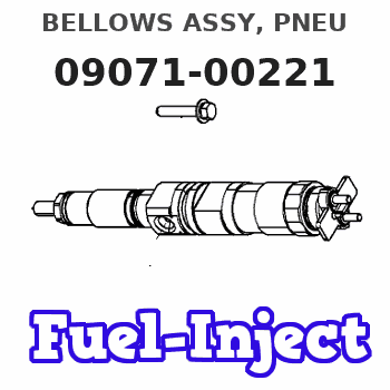
Information bellows assy, pneu
Rating:
Scheme ###:
| 000. | [01] | 09071-00221 | BELLOWS ASSY, PNEU | 22680-54351 |
| 001. | [01] | 09644-00770 | COVER SUB-ASSY, GO | 22703-54351 |
| 002. | [01] | 09071-60120 | COVER | 22682-54351 |
| 003. | [01] | 09071-10070 | BELLOWS SUB-ASSY, | 22681-54460 |
| 004. | [01] | 09646-90020 | R0D SUB-ASSY, PUSH | 22301-54350 |
| 005. | [01] | 09611-80080 | BUSHING, GUIDE | 22348-64400 |
| 006. | [01] | 09611-80020 | BUSHING, GUIDE | 22348-54121 |
| 007. | [01] | 09645-50090 | PIN, LEVER CONECTI | 22338-54120 |
| 008. | [01] | 09625-40021 | NUT, GOVERNOR SHAF | 22722-54120 |
| 009. | [01] | 09604-90230 | O-RING | 22193-55031 |
| 010. | [01] | 94901-81680 | WASHER, COPPER PLA | 90099-01473 |
| 011. | [01] | 09629-50680 | LEVER SUB-ASSY, CO | 22308-17570 |
| 011. | [01] | 09629-50080 | LEVER SUB-ASSY, CO | 22308-54140 |
| 012. | [01] | 09627-20040 | PIN, LEVER SUPPORT | 22526-54120 |
| 013. | [02] | 09626-90032 | BOLT, GOVERNOR LIN | 22739-54120 |
| 014. | [02] | 09024-80010 | WASHER, DRAIN SCRE | 22378-76010 |
| 014. | [02] | 09642-60110 | GASKET, DELIVERY V | 22149-6D450 |
| 015. | [01] | 09031-70130 | PLUG, SCREW | 22129-54120 |
| 016. | [01] | 09024-10010 | WASHER, AIR BLEEDE | 22119-77020 |
| 017. | [01] | 94905-04070 | NUT, HEXAGON | 90099-05156 |
| 018. | [01] | 09646-60050 | SPRING | 22327-54120 |
| 019. | [01] | 09646-80020 | CAP RUBBER | 22777-54120 |
| 020. | [04] | 09644-90130 | BOLT, SOCKET | 22395-54263 |
| 021. | [01] | 94914-03610 | O-RING | 90099-14057 |
| 022. | [02] | 09621-70040 | WASHER, TIMER ADJU | 22622-54010 |
Include in #3:
Cross reference number
| Part num | Firm num | Firm | Name |
| 09071-00221 | 22680-5435 | BELLOWS ASSY, PNEU |
Information:
(3) Torque for locknut for valve adjustment screw ... 30 4 N m (22 3 lb ft)(4) Torque for locknut for bridge assembly ... 30 4 N m (22 3 lb ft)Bridge Installation Instructions:a. Lubricate bridge dowel, bridge bore and top pad of bridge with engine oil.b. Install bridge assembly on bridge dowel.c. While firmly pressing [0.5 to 4.5 kg (1 to 10 lb)] straight down on the bridge pad, turn the adjusting screw clockwise until contact is made with the valve stem.d. Turn the screw clockwise and additional 20 to 30° (1/3 to 1/2 of 1 hex on nut) to straighten the dowel in the guide and compensate for slack in the threads.e. Hold the adjusting screw in this position and tighten the locknut to a torque of 30 4 N m (22 3 lb ft).(5) Valve clearance (with engine stopped). Intake valves ... 0.38 mm (.015 in)Exhaust valves ... 0.76 mm (.030 in) After setting valve clearance, tighten adjusting screw locknut to a torque of 30 4 N m (22 3 lb ft). Then, recheck the valve clearance.(5) Clearance for valves: Intake valves ... 0.38 mm (.015 in)Exhaust valves ... 0.76 mm (.030 in)(6) Height to top of dowel ... 53.3 0.5 mm (2.10 .02 in)(7) Diameter of dowel ... 11.008 0.003 mm (.4334 .0001 in) Bore in bridge for dowel ... 11.13 0.05 mm (.438 .002 in)Bore in head for dowel ... 10.968 0.020 mm (.4318 .0008 in) (8) Diameter of valve lifter ... 27.896 0.013 mm (1.0983 .0005 in) Bore in block for valve lifter ... 27.953 0.019 mm (1.1005 .0008 in) See Guideline For Reusable Parts; Salvage Of Lifter Bores In 3400 Family Engines, Form No. SEBF8069 for the procedure, tooling and specifications needed to install 4W4588 Sleeves for salvage of the lifter bores in the cylinder block.(9) 6N6872 Lifter Guide Spring. See Guideline For Reusable Parts, Form No. SEBF8066, for information on using guide springs again. (10) 2N7229 Spring: Length under test force ... 74.2 mm (2.92 in)Test force ... 45 to 53 N (10 to 12 lb)Free length after test ... 114.3 mm (4.50 in)Outside diameter ... 29.7 mm (1.17 in)(11) Dowel length above top surface of rocker shaft support to be ... 12.7 1.0 mm (.50 .04 in)(12) Clearance for rocker arms (both ends) ... 0.30 to 1.40 mm (.012 to .055 in)(13) Use 2N7228 Washer as needed to get clearance (12).