Information governor assy, com
Rating:
KIT List:
| Governor assy, com | 1908900230 |
| Governor assy, com | 1908900230 |
Scheme ###:
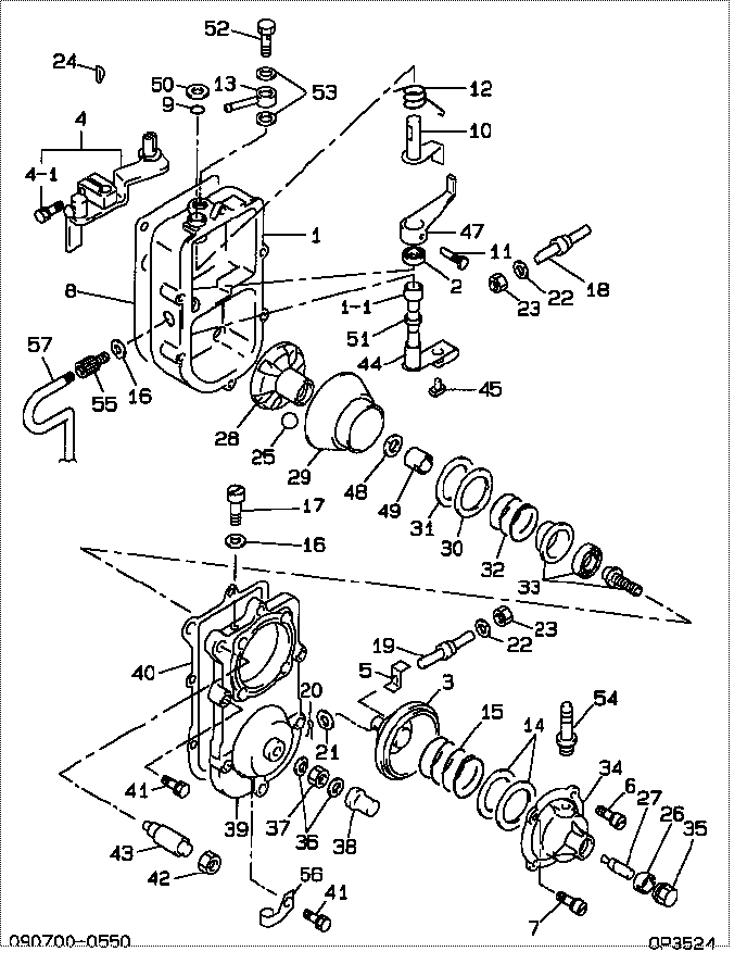
| 000. | [01] | 09070-00550 | GOVERNOR ASSY, COM | 22320-58051 |
| 001. | [01] | 09051-00151 | HOUSING SUB-ASSY, | 22306-56040 |
| 001-001. | [01] | 09051-30101 | BUSHING | |
| 002. | [01] | 06223-70010 | SEAL, OIL | 85613-31010 |
| 003. | [01] | 09058-00041 | DIAPHRAGM SUB-ASSY | 22303-47010 |
| 004. | [01] | 09053-01070 | LEVER SUB-ASSY, IN | 22308-56061 |
| 004-001. | [01] | 91518-05161 | BOLT, W/WASHER | |
| 005. | [01] | 09009-20060 | BRACKET | 22178-56011 |
| 006. | [03] | 94900-72430 | SCREW, W/WASHER | 90099-00936 |
| 007. | [01] | 94904-61430 | BOLT | 90099-04945 |
| 008. | [01] | 09082-30460 | GASKET | 22442-58260 |
| 009. | [01] | 90801-10080 | O-RING | 96711-19008 |
| 010. | [01] | 09115-90150 | ARM SUB-ASSY | 21408-68010 |
| 011. | [01] | 09055-30020 | BOLT, GOVERNOR STO | 22332-77021 |
| 012. | [01] | 09055-40180 | SPRING, DIAPHRAGM | 22333-56040 |
| 013. | [01] | 09264-20090 | UNION | 90099-81013 |
| 014. | [2C] | 09061-60050 | SHIM, MAIN SPRING | 22364-76010 |
| 014. | [2C] | 09061-60060 | SHIM, MAIN SPRING | 22363-76010 |
| 014. | [2C] | 09061-60070 | SHIM, MAIN SPRING | 22362-76010 |
| 014. | [2C] | 09061-60080 | SHIM, MAIN SPRING | 22361-76010 |
| 015. | [01] | 09061-50510 | SPRING, GOVERNOR M | 22326-58010 |
| 016. | [02] | 09024-80010 | WASHER, DRAIN SCRE | 22378-76010 |
| 017. | [01] | 09078-20010 | SCREW | 22386-46010 |
| 018. | [01] | 09057-30070 | BOLT, DIAPHRAGM CO | 22329-77130 |
| 019. | [01] | 09057-30050 | BOLT, DIAPHRAGM CO | 22329-77021 |
| 020. | [01] | 90400-02101 | PIN, SPLIT | 90095-02001 |
| 021. | [01] | 90200-06001 | WASHER, PLATE | 90093-00602 |
| 022. | [02] | 90258-05001 | WASHER, SPRING | 90032-04023 |
| 023. | [02] | 91170-05321 | NUT, HEXAGON | 90092-20582 |
| 024. | [01] | 94913-00010 | KEY, WOODRUFF | 90099-13001 |
| 025. | [06] | 94912-00260 | BALL, STEEL | 90099-12010 |
| 026. | [01] | 09064-50010 | NUT, GOVERNOR IDRI | 22319-77010 |
| 027. | [01] | 09063-00170 | CAPSULE, IDLING | 22318-48030 |
| 028. | [01] | 09065-50020 | GUIDE, BALL | 22693-77130 |
| 029. | [01] | 09073-00030 | SLIDER SUB-ASSY | 22692-56041 |
| 030. | [01] | 94901-35120 | WASHER, PLATE, SK | 90099-01441 |
| 031. | [01] | 09066-40040 | SHEET, SPRING | 22696-56040 |
| 032. | [01] | 09099-20521 | SPRING, SPEED CONT | 22449-48030 |
| 033. | [01] | 09065-60010 | BEARING SUB-ASSY | 22694-77130 |
| 034. | [01] | 09062-10160 | HOUSING, GOVERNOR | |
| 035. | [01] | 09109-40140 | CAP, LEVER | 22457-58010 |
| 036. | [02] | 94901-81020 | WASHER, COPPER PLA | 90201-08106 |
| 037. | [01] | 94905-03390 | NUT, HEXAGON | 90099-05173 |
| 038. | [01] | 09103-10020 | NUT, CAP | 22437-77130 |
| 039. | [01] | 09101-11090 | COVER, GOVERNOR | 22703-56040 |
| 040. | [01] | 09082-30350 | GASKET | 22442-77130 |
| 041. | [06] | 91418-06251 | BOLT, W/WASHER | 90091-20605 |
| 042. | [01] | 94905-30040 | NUT, HEXAGON, W/ H | 90099-05056 |
| 043. | [01] | 09056-00110 | CAPSULE, FULL STOP | 22336-68010 |
| 044. | [01] | 09066-00020 | ARM SUB-ASSY | |
| 045. | [01] | 09066-20020 | PIN, SHIFTING | 22698-77131 |
| 047. | [01] | 09053-00890 | LEVER SUB-ASSY, IN | |
| 048. | [01] | 94901-50500 | WASHER, SPRING | 22348-76010 |
| 049. | [01] | 09084-40010 | NUT, ROUND | 22451-77123 |
| 050. | [01] | 94901-34330 | WASHER, PLATE, SK | 90099-01445 |
| 051. | [01] | 94901-34190 | WASHER, PLATE, SK | |
| 052. | [01] | 94918-00050 | SCREW, HOLLOW | 90401-12006 |
| 053. | [02] | 09024-10010 | WASHER, AIR BLEEDE | 22119-77020 |
| 054. | [01] | 09062-40040 | UNION, VENTURI PIP | 90404-58030 |
| 055. | [01] | 09025-00280 | NIPPLE SUB-ASSY, O | 22197-58022 |
| 056. | [01] | 94935-03042 | CLIP, CORD | 90099-35023 |
| 057. | [01] | 70311-99016 | HOSE, VACUUM | 95411-19916 |
Include in #3:
09070-00550
as GOVERNOR ASSY, COM
Cross reference number
| Part num | Firm num | Firm | Name |
| 09070-00550 | 22320-5805 | GOVERNOR ASSY, COM | |
| 22320-58051 | TOYOTA | GOVERNOR ASSY, COM |
Information:
Emergency Stopping
Emergency shutoff controls are for EMERGENCY use ONLY. DO NOT use Emergency shutoff devices or controls for normal stopping procedure.
Make sure that any external system components that have been operating to support engine operation are secured after any stop.Emergency Stop Buttons
Emergency Stop Button, shown mounted on a junction box.Emergency stops may be made by pushing the Emergency Stop Button located on the junction box (if equipped). Both the Button and the air inlet shutoff (if equipped) require resetting before the engine will start.Manual Stopping
A manual shutoff shaft is provided to override the governor control. The shaft will move the fuel control linkage to the FUEL OFF position. Refer to the Model Views for the engine location of the shaft. The engine may be stopped by using the shaft and the Woodward Actuator (if equipped) or the Mechanical Governor (if equipped).
Typical Woodward Actuator Control Lever.If equipped with a Woodward Actuator, move the control lever to the FUEL OFF position.
Typical Mechanical Governor ControlIf equipped with a Mechanical Governor Control, move the control to the FUEL OFF position.Hold the lever at the FUEL OFF position until the engine stops.Air Shutoff (If Equipped)
Some engines are equipped with an air shutoff, located between the aftercooler and the turbocharger. If equipped with an air shutoff lever, move the lever to the OFF position.Manual Stop Procedure
There may be several ways to shut off your engine. Make sure the shutoff procedures are understood. Use the following general guidelines for stopping the engine.1. Disengage any driven equipment or remove the load from engine.2. Allow the engine to run at rated speed for five minutes.3. Run the engine at 1/2 rated speed for two to three minutes.4. Reduce the engine speed to low idle for 30 seconds.Check the crankcase oil level during the engine idle. Read the LOW IDLE side of the dipstick. Maintain the oil level between the ADD and FULL marks.5. Shut the engine off by turning the start/stop switch to the stop or off position.After Stopping the Engine
* Check the crankcase oil level. Maintain the oil level between the ADD and FULL marks in the FULL RANGE zone on the dipstick.* Repair any leaks, perform minor adjustments, tighten loose bolts, etc.* Note the service hour meter reading. Perform periodic maintenance as instructed in the Maintenance Schedule.* Fill the fuel tank to prevent accumulation of moisture in the fuel. Do not overfill.
Only use antifreeze/coolant mixtures recommended in the Cooling System Specifications of this manual. Failure to do so can cause engine damage.
* Allow the radiator and engine jacket water system to cool. Check the coolant level. Maintain the cooling system to 13 mm (1/2 inch) from bottom of the fill pipe.If freezing temperatures are expected, check the coolant for proper antifreeze protection. The cooling system must be protected against freezing to the lowest expected ambient (outside) temperature. Add the proper coolant and water mixture if necessary.