Information governor assy, inj
Rating:
KIT List:
| Governor assy, inj | 1908900260 |
| Governor assy, inj | 1908900260 |
Scheme ###:
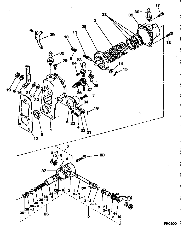
| 000. | [01] | 09050-01010 | GOVERNOR ASSY, INJ | |
| 001. | [01] | 09051-00110 | HOUSING SUB-ASSY, | 22306-87303-000 |
| 002. | [01] | 09078-00240 | GOVERNOR KIT, PNEU | 22370-87301-000 |
| 002-001. | [01] | 09078-30030 | HOUSING, LEVER | 22312-47010-000 |
| 002-002. | [01] | 09077-60023 | SHAFT, GOVERNOR | 22384-48010-000 |
| 002-003. | [01] | 09077-70030 | CAM | 22385-47010-000 |
| 002-004. | [01] | 09055-30020 | BOLT, GOVERNOR STO | 22332-77021-000 |
| 002-005. | [02] | 94914-00600 | O-RING | 90099-14025-000 |
| 002-006. | [02] | 94901-33730 | WASHER, PLATE, SK | 22375-76010-000 |
| 002-007. | [01] | 94907-10070 | WASHER, SNAP | 90099-07015-000 |
| 002-008. | [01] | 94919-20960 | COLLAR, STEEL | 90099-19210-000 |
| 002-009. | [01] | 09078-60070 | SPRING, BACK | |
| 002-010. | [01] | 09053-11032 | LEVER, PNEUMATIC G | |
| 003. | [01] | 09061-50491 | SPRING, GOVERNOR M | 22326-87304-000 |
| 004. | [01] | 90050-06081 | SCREW, CROSSRECESS | 90090-50609-000 |
| 005. | [01] | 94915-00050 | SEAL, OIL | 90099-15003-000 |
| 005. | [01] | 94915-01750 | SEAL, OIL | 90099-15003-000 |
| 006. | [01] | 09052-50010 | COVER, CAMSHAFT | 22335-77020-000 |
| 007. | [03] | 91510-05081 | BOLT, W/WASHER | 93381-15008-000 |
| 008. | [01] | 90258-05001 | WASHER, SPRING | 22370-87301-000 |
| 009. | [01] | 90258-08001 | WASHER, SPRING | 22312-47010-000 |
| 010. | [01] | 90190-08651 | NUT, HEXAGON | 94110-40800-000 |
| 011. | [01] | 09057-30050 | BOLT, DIAPHRAGM CO | 22329-77021-000 |
| 012. | [01] | 09082-30210 | GASKET | 22442-77131-000 |
| 012. | [01] | 09082-30360 | GASKET | 22442-77131-000 |
| 012. | [01] | 09082-30460 | GASKET | |
| 013. | [01] | 91170-05321 | NUT, HEXAGON | 90092-20582-000 |
| 014. | [01] | 90200-06001 | WASHER, PLATE | 94611-00600-000 |
| 015. | [01] | 90400-02101 | PIN, SPLIT | 90095-02002-000 |
| 016. | [01] | 09053-00430 | LEVER SUB-ASSY, IN | 22308-87304-000 |
| 017. | [01] | 94904-61430 | BOLT | 90099-04945-000 |
| 018. | [03] | 94900-72430 | SCREW, W/WASHER | 90099-00936-000 |
| 019. | [02] | 90400-02151 | PIN, SPLIT | 90095-02004-000 |
| 020. | [01] | 09054-10110 | SHAFT, GOVERNOR ST | 22391-87301-000 |
| 021. | [02] | 90200-08211 | WASHER, PLATE | 22113-87701-000 |
| 022. | [ C] | 94901-14850 | WASHER, STEEL PLAT | 22376-76010-000 |
| 022. | [ C] | 94901-14860 | WASHER, STEEL PLAT | 22377-76010-000 |
| 023. | [01] | 09055-10030 | LEVER, GOVERNOR ST | 22392-87301-000 |
| 024. | [01] | 09055-30020 | BOLT, GOVERNOR STO | 22332-77021-000 |
| 025. | [01] | 09055-40011 | SPRING, DIAPHRAGM | 22333-77020-000 |
| 026. | [01] | 09056-00110 | CAPSULE, FULL STOP | 22336-68010-000 |
| 027. | [01] | 94905-60781 | NUT | 90099-05153-000 |
| 028. | [01] | 09058-00041 | DIAPHRAGM SUB-ASSY | 22303-47010-000 |
| 029. | [01] | 09078-20010 | SCREW | 22386-46010-000 |
| 030. | [02] | 09062-40010 | UNION, VENTURI PIP | 90404-12018-000 |
| 032. | [02] | 09024-80010 | WASHER, DRAIN SCRE | 22378-87701-000 |
| 033. | [ C] | 09061-60050 | SHIM, MAIN SPRING | 22364-76010-000 |
| 033. | [ C] | 09061-60060 | SHIM, MAIN SPRING | 22363-76010-000 |
| 033. | [ C] | 09061-60070 | SHIM, MAIN SPRING | 22362-76010-000 |
| 033. | [ C] | 09061-60080 | SHIM, MAIN SPRING | 22361-76010-000 |
| 034. | [01] | 94914-00600 | O-RING | 90099-14025-000 |
| 035. | [01] | 09062-10110 | HOUSING, GOVERNOR | 22323-87303-000 |
| 036. | [01] | 09063-00130 | CAPSULE, IDLING | |
| 036-001. | [01] | 90567-16000 | RING, HOLE SNAP | 96151-01600-000 |
| 036-002. | [ C] | 94901-31960 | WASHER, PLATE, SK | 90099-02315-000 |
| 036-002. | [ C] | 94901-31970 | WASHER, PLATE, SK | 90099-02316-000 |
| 036-002. | [ C] | 94901-31980 | WASHER, PLATE, SK | 90099-01381-000 |
| 036-002. | [ C] | 94901-31990 | WASHER, PLATE, SK | 90099-01382-000 |
| 036-003. | [01] | 09064-30041 | ROD, PUSH | 22321-47010-000 |
| 036-004. | [ C] | 94901-32610 | WASHER, PLATE, SK | 90099-01351-000 |
| 036-004. | [ C] | 94901-33840 | WASHER, PLATE, SK | 22621-46010-000 |
| 036-005. | [01] | 09063-20240 | SPRING, GOVERNOR I | 22356-87302-000 |
| 036-006. | [01] | 09063-10041 | SLEEVE, IDLING SPR | 22316-47010-000 |
| 036-007. | [01] | 09063-90010 | SPRING, RETURN | 22322-47010-000 |
| 036-008. | [01] | 94907-20630 | RING, SNAP | 90099-07093-000 |
| 037. | [01] | 09078-70030 | GASKET, GOVERNOR C | 22346-47010-000 |
| 038. | [02] | 94904-72520 | BOLT, W/WASHER | |
| 039. | [01] | 09069-00070 | BRACKET SUB-ASSY, | 22307-46010-000 |
Include in #3:
09050-01010
as GOVERNOR ASSY, INJ
Cross reference number
| Part num | Firm num | Firm | Name |
| 09050-01010 | GOVERNOR ASSY, INJ | ||
| 22310-87C -000 | DAIHATSU | GOVERNOR ASSY, INJ |
Information:
Introduction
The tool group and seating procedure has been developed to provide improved seating of injector cones in cylinder head brass sleeves. The tool is designed for 3114, 3116, or 3126 MUI Engines and 3116 or 3126 HEUI 2-Valve Engine injectors. There is a separate procedure for both the MUI and HEUI engines. The procedures can be done with the rocker arms removed and the intake manifold on the head. They can also be used with both the rocker arms and intake manifold removed.These procedures assumes that new sleeves have been installed, but NOT reamed, or existing sleeves have been inspected for pitting or carbon tracking and reamed for clean up, if required.
Illustration 1. 173-1530 Injector Seating Tool Group. See Chart A for item identification and part numbers. MUI Engine Procedure
This procedure can be used for 3114, 3116, and 3126 MUI Engines.1. Install a new injector brass sleeve or inspect and ream the existing sleeves as outlined in Tool Operating Manual NEHS0675. It is not necessary to ream new sleeves when using this procedure.2. Install the unit injector and align the rack bar. Do not use the small O-ring on the injector tip.3. Install holding clamp bolt (12) and tighten to 12 3 N m, 1.2 0.3 meter kg, (9 2 lb. ft.).
Illustration 2. Install Holding Clamp Bolt (12).4. Remove inlet manifold bolt (13) closest to the injector.
For a repair procedure, remove only one manifold bolt at a time. Removing all the manifold bolts could weaken or damage the manifold/head gasket material.
Illustration 3. Remove Inlet Manifold Bolt (13).5. Install MUI injector forcing cover (7) over the injector. The milled surface should line up with injector clamp bolt. The two long flat surfaces are for valve spring clearance. Refer to the "MUI Tooling" section for a warning on the sharp edges of this tool.
Make sure the slots of injector forcing cover (7) are free of nicks, scratches, or burrs. Damage in the slots will result in damage to the injector spring.
Illustration 4. Install Injector Forcing Cover.
Illustration 5. MUI Injector Forcing Cover Properly Installed.6. If assembled, back out forcing bolt (4) in forcing bridge (1) to provide clearance between the injector forcing cover and forcing bridge.7. Place a small amount of 4C-5591 Thread Lubricant on top of the injector forcing cover's wear button (10) and on the threads of forcing bolt (4).
Complete lubrication of the wear button and forcing bolt must be maintained for each injector seating procedure. Failure to relubricate each part before seating the next injector may cause premature wear or tool damage. Also, make sure the forcing bolt turns freely and does not have any damaged threads.
8. Install the forcing bridge with three 7X-0457 Bolts (5) and three 9M-1974 Hard Washers (6). Put the two long legs of the forcing bridge in the two rocker arm shaft support holes closest to the injector. The short leg of the forcing bridge with spacer (2) installed sits on the intake manifold bolt boss. [The long spacer (3)