Information governor assy, inj
Rating:
Scheme ###:
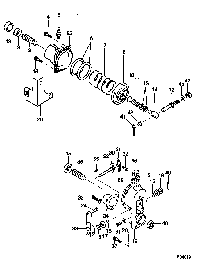
| 000. | [01] | 09050-00183 | GOVERNOR ASSY, INJ | |
| 000. | [01] | 09050-00183 | GOVERNOR ASSY, INJ | 22310-76012 |
| 002. | [01] | 09063-00010 | CAPSULE, IDLING | |
| 002. | [01] | 09063-00010 | CAPSULE, IDLING | 22318-76010 |
| 003. | [01] | 09064-50010 | NUT, GOVERNOR IDRI | |
| 003. | [01] | 09064-50010 | NUT, GOVERNOR IDRI | 22319-77010 |
| 004. | [01] | 09069-80030 | SCREW, DIAPHRAGM H | |
| 004. | [01] | 09069-80030 | SCREW, DIAPHRAGM H | 22357-76011 |
| 005. | [02] | 09062-40010 | UNION, VENTURI PIP | 90404-12018 |
| 005. | [02] | 09062-40010 | UNION, VENTURI PIP | |
| 006. | [ C] | 09061-60060 | SHIM, MAIN SPRING | 22363-76010 |
| 006. | [ C] | 09061-60070 | SHIM, MAIN SPRING | 22362-76010 |
| 006. | [ C] | 09061-60080 | SHIM, MAIN SPRING | 22361-76010 |
| 006. | [ C] | 09061-60060 | SHIM, MAIN SPRING | |
| 006. | [ C] | 09061-60050 | SHIM, MAIN SPRING | |
| 006. | [ C] | 09061-60080 | SHIM, MAIN SPRING | |
| 006. | [ C] | 09061-60070 | SHIM, MAIN SPRING | |
| 006. | [ C] | 09061-60050 | SHIM, MAIN SPRING | 22364-76010 |
| 007. | [01] | 09061-50010 | SPRING, GOVERNOR M | 90501-15128 |
| 007. | [01] | 09061-50010 | SPRING, GOVERNOR M | |
| 008. | [01] | 09058-00011 | DIAPHRAGM SUB-ASSY | 22303-77020 |
| 008. | [01] | 09058-00011 | DIAPHRAGM SUB-ASSY | |
| 010. | [ C] | 09060-60020 | SEAT, ADAPTER SPRI | 22367-76010 |
| 010. | [ C] | 09060-60040 | SEAT, ADAPTER SPRI | 22369-76010 |
| 010. | [ C] | 09060-60030 | SEAT, ADAPTER SPRI | 22368-76010 |
| 010. | [ C] | 09060-60010 | SEAT, ADAPTER SPRI | 22366-76010 |
| 010. | [ C] | 09060-60020 | SEAT, ADAPTER SPRI | |
| 010. | [ C] | 09060-60040 | SEAT, ADAPTER SPRI | |
| 010. | [ C] | 09060-60010 | SEAT, ADAPTER SPRI | |
| 010. | [ C] | 09060-60030 | SEAT, ADAPTER SPRI | |
| 011. | [01] | 09061-10010 | SPRING, GOVERNOR A | |
| 011. | [01] | 09061-10010 | SPRING, GOVERNOR A | 90501-08142 |
| 012. | [01] | 09057-30050 | BOLT, DIAPHRAGM CO | |
| 012. | [01] | 09057-30050 | BOLT, DIAPHRAGM CO | 22329-77021 |
| 013. | [2C] | 94901-14840 | WASHER, STEEL PLAT | |
| 013. | [2C] | 94901-14830 | WASHER, STEEL PLAT | |
| 013. | [2C] | 94901-14840 | WASHER, STEEL PLAT | 22374-76010 |
| 013. | [2C] | 94901-14820 | WASHER, STEEL PLAT | |
| 013. | [2C] | 94901-14810 | WASHER, STEEL PLAT | |
| 013. | [2C] | 94901-14820 | WASHER, STEEL PLAT | 22372-76010 |
| 013. | [2C] | 94901-14830 | WASHER, STEEL PLAT | 22373-76010 |
| 013. | [2C] | 94901-14810 | WASHER, STEEL PLAT | 22371-76010 |
| 014. | [01] | 09060-10030 | PIN, GOVERNOR ADAP | 22328-77020 |
| 014. | [01] | 09060-10030 | PIN, GOVERNOR ADAP | |
| 015. | [02] | 94914-00600 | O-RING | |
| 015. | [02] | 94914-00600 | O-RING | 90099-14025 |
| 016. | [02] | 94901-33730 | WASHER, PLATE, SK | |
| 016. | [02] | 94901-33730 | WASHER, PLATE, SK | 22375-76010 |
| 017. | [2C] | 94901-14850 | WASHER, STEEL PLAT | |
| 017. | [2C] | 94901-14850 | WASHER, STEEL PLAT | 22376-76010 |
| 017. | [2C] | 94901-14860 | WASHER, STEEL PLAT | 22377-76010 |
| 017. | [2C] | 94901-14860 | WASHER, STEEL PLAT | |
| 019. | [01] | 09051-00110 | HOUSING SUB-ASSY, | |
| 019. | [01] | 09051-00110 | HOUSING SUB-ASSY, | 22306-48010 |
| 020. | [02] | 09024-80010 | WASHER, DRAIN SCRE | 22121-30890-71 |
| 020. | [02] | 09024-80010 | WASHER, DRAIN SCRE | 22378-76010 |
| 021. | [01] | 90000-06081 | SCREW, SLOTTED PAN | 90090-00601 |
| 021. | [01] | 90000-06081 | SCREW, SLOTTED PAN | |
| 022. | [01] | 09054-10070 | SHAFT, GOVERNOR ST | 22334-77050 |
| 022. | [01] | 09054-10070 | SHAFT, GOVERNOR ST | |
| 023. | [01] | 94913-00010 | KEY, WOODRUFF | 90099-13001 |
| 023. | [01] | 94913-00010 | KEY, WOODRUFF | |
| 024. | [01] | 09053-50010 | PIN, ADJUST LEVER | 22338-77020 |
| 024. | [01] | 09053-50010 | PIN, ADJUST LEVER | |
| 025. | [01] | 09062-10160 | HOUSING, GOVERNOR | |
| 025. | [01] | 09062-10160 | HOUSING, GOVERNOR | |
| 028. | [01] | 09069-00010 | BRACKET SUB-ASSY, | 22307-77020 |
| 028. | [01] | 09069-00010 | BRACKET SUB-ASSY, | |
| 030. | [01] | 09055-40011 | SPRING, DIAPHRAGM | |
| 030. | [01] | 09055-40011 | SPRING, DIAPHRAGM | 22333-77020 |
| 031. | [01] | 09055-10030 | LEVER, GOVERNOR ST | 22331-77021 |
| 031. | [01] | 09055-10030 | LEVER, GOVERNOR ST | |
| 032. | [01] | 09055-30020 | BOLT, GOVERNOR STO | 22332-77021 |
| 032. | [01] | 09055-30020 | BOLT, GOVERNOR STO | |
| 033. | [03] | 94904-10850 | BOLT, SLOTTED HEXA | 90099-04266 |
| 033. | [03] | 94904-10850 | BOLT, SLOTTED HEXA | |
| 034. | [01] | 09052-50010 | COVER, CAMSHAFT | 22335-77020 |
| 034. | [01] | 09052-50010 | COVER, CAMSHAFT | 22335-70020 |
| 035. | [01] | 94905-30040 | NUT, HEXAGON, W/ H | 90099-05056 |
| 035. | [01] | 94905-30040 | NUT, HEXAGON, W/ H | |
| 036. | [01] | 09056-90010 | SCREW, FULL STOP | 22382-76010 |
| 036. | [01] | 09056-90010 | SCREW, FULL STOP | |
| 037. | [04] | 94904-71380 | BOLT, W/WASHER | |
| 037. | [04] | 94904-71380 | BOLT, W/WASHER | 90099-04563 |
| 038. | [01] | 09053-00110 | LEVER SUB-ASSY, IN | |
| 038. | [01] | 09053-00110 | LEVER SUB-ASSY, IN | 22308-77021 |
| 040. | [01] | 94915-01750 | SEAL, OIL | |
| 040. | [01] | 94915-01750 | SEAL, OIL | |
| 041. | [01] | 90400-02101 | PIN, SPLIT | 90095-02001 |
| 041. | [01] | 90400-02101 | PIN, SPLIT | 22144-73600-71 |
| 042. | [01] | 90200-06001 | WASHER, PLATE | 90093-00602 |
| 042. | [01] | 90200-06001 | WASHER, PLATE | |
| 043. | [01] | 09109-40140 | CAP, LEVER | 22457-58010 |
| 043. | [01] | 09109-40140 | CAP, LEVER | |
| 045. | [01] | 90258-05001 | WASHER, SPRING | 94511-00500 |
| 045. | [01] | 90258-05001 | WASHER, SPRING | 90032-04023 |
| 046. | [01] | 09078-20010 | SCREW | 22386-46010 |
| 046. | [01] | 09078-20010 | SCREW | |
| 047. | [01] | 90170-05361 | NUT, HEXAGON | |
| 047. | [01] | 90170-05361 | NUT, HEXAGON | 90092-20502 |
| 048. | [03] | 94900-72430 | SCREW, W/WASHER | |
| 048. | [03] | 94900-72430 | SCREW, W/WASHER | 90099-00936 |
| 049. | [02] | 90400-02151 | PIN, SPLIT | |
| 049. | [02] | 90400-02151 | PIN, SPLIT |
Include in #3:
Cross reference number
| Part num | Firm num | Firm | Name |
| 09050-00183 | GOVERNOR ASSY, INJ |
Information:
Dismantling And Installing The Fuel-Injection Pump (As from 3 cylinder engine)
It is assumed that the vee-belt tensioner or cover is dismantled. Dismantling:
1. Disconnect the fuel line attached to the solenoid valve. Disconnect the flexible tubing delivering fuel to the feed pump and injection pump. Dismantle the fuel line connecting the fuel filter with the injection pump. Disconnect the leak-off line and the fuel delivery lines attached to the injection pump.
7-9 Immediately the pipes are disconnected, plug the bores and fit caps over the connecting stubs of the fuel system.Fig. 7-9
7-102. Unscrew the nuts securing the injection pump drive to the injection pump shaft. (For slotted nut use double spanner No. 110330).Fig. 7-103. Remove the spring lockwasher. Make sure that it does not drop into the crankcase. Important:As from 1975, the hub was modified in the case of rigid drive.(The thread for attachment of universal device No. 110340 with sleeve has been omitted).See: DISMANTLING AND INSTALLING INJECTION PUMP WITH MODIFIED HUB FOR RIGID DRIVE (as from 3-cylinder engine)4. Remove gearwheel fastening screws.
7-115. If the engine has an injection timer mount the tool without sleeve on the injection pump drive. If the engine has no injection timer, mount the tool with sleeve on the injection pump drive. (Universal device No. 110340).Fig. 7-11
7-126. Pull the injection pump drive from the injection pump shaft.Fig. 7-12 left and right Do not rotate the crankshaft.7. Unscrew the nuts on the injection pump and remove the injection pump. Remove the rubber O-seal on the injection pump. If necessary, dismantle the cut-out system attached to the injection pump.Installing:
7-131. Re-install the automatic stop system removed from the injection pump.Fig. 7-132. Check whether the Woodruff key is fitted to the injection pump shaft. If it is not, install one.
7-143. Assemble a new rubber O-seal to the injection pump.Fig. 7-14
7-154. Install the injection pump so that the Woodruff key in the injection pump shaft engages in the groove of the injection pump drive and the connections for the fuel delivery lines face diagonally upwards.Fig. 7-15
7-165. Line up the notches in the injection pump and intermediate flange. Assemble the nuts.Fig. 7-16
7-176. Screw the nuts on the fuel-injection pump drive. (Use a 19 mm socket spanner or double spanner No. 110330).Fig. 7-17 Attention:Slotted nut replaced as from 1977 by clamping nut 13a/fl. For tightening instructions, see Technical Data.
7-187. Assemble and tighten the union of the injection delivery line, so that the latter is free from tension.Fig. 7-18
7-198. Connect the leak-off line and the line connecting with the solenoid valve, and at the same time fit a new gasket.Fig. 7-199. Assemble new gaskets and connect the fuel pipes or flexible tubing leading from the fuel feed pump to the delivery filter and from this filter to the injection pump.
7-2010. If the engine is equipped with an automatic cut-out, install the return spring thereof.Fig. 7-2011. Adjust the fuel-injection point in accordance with the instructions given in this manual. (See Section 2).Dismantling And Installing Injection Pump With Modified Hub For Rigid Drive (as from