Information cover, bearing
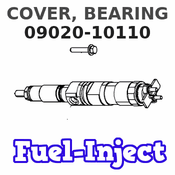
COVER, BEARING
DA
- * THIS PART CAN BE USED IN CASE THE CAMSHAFT HAS BEEN
- WORN.
- * NO.1 IS A SELECT USE PART DEPEND ON THE CAMSHAFT
- DIAMETER.
- * THESE PARTS CAN BE USED WHEN REPAIRING THE PUMP.
Rating:
Scheme ###:
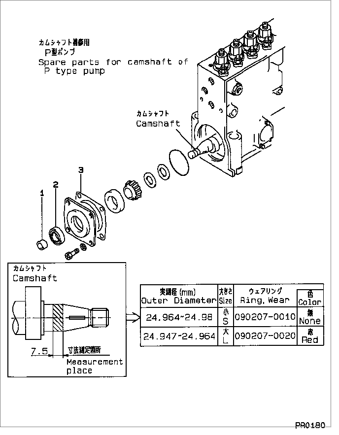
| 000. | [01] | 09020-10000 | COVER, BEARING | |
| 000. | [01] | 09020-10000 | COVER, BEARING | |
| 000. | [01] | 09020-10000 | COVER, BEARING | |
| 001. | [1C] | 09020-70020 | RING, WEAR | |
| 001. | [1C] | 09020-70010 | RING, WEAR | |
| 001. | [1C] | 09020-70020 | RING, WEAR | ME702719 |
| 001. | [1C] | 09020-70010 | RING, WEAR | ME702718 |
| 001. | [1C] | 09020-70020 | RING, WEAR | 22143-1100A |
| 001. | [1C] | 09020-70010 | RING, WEAR | 22143-1090A |
| 002. | [01] | 94915-02010 | SEAL, OIL | ME702702 |
| 002. | [01] | 94915-02010 | SEAL, OIL | |
| 002. | [01] | 94915-02010 | SEAL, OIL | |
| 003. | [01] | 09020-10580 | COVER, BEARING | |
| 003. | [01] | 09020-10580 | COVER, BEARING | ME702701 |
| 003. | [01] | 09020-10580 | COVER, BEARING |
Include in #3:
09010-01072
as COVER, BEARING
Cross reference number
| Part num | Firm num | Firm | Name |
| 09020-10110 | 22111-1190 | COVER, BEARING | |
| 22111-1190A | HINO | COVER, BEARING |
Information:
start by: a) remove fuel injection pumpsb) separation of governor from fuel injection pump housingc) remove fuel transfer pump1. Loosen the screws that hold the levers to the shaft assembly. 2. Remove the screw (1) that holds the lever assembly (2) to the shaft assembly. 3. Remove the shaft assembly (5) from the housing and remove the levers (3) and lever assembly (2).4. Loosen the screws that hold the levers (6) to the shaft.5. Remove the screw that holds the lever (4) to the shaft.6. Remove the shaft (7) from the housing and remove the levers. 7. Remove the lifter and roller assemblies (8) from the housing with a magnet. Put identification on the lifters (10) and rollers (9) for installation in their respective bores in the housing. 8. Remove the camshaft (11) from the housing.
Do not use a force to remove the camshaft. Turn the camshaft to permit the free passage of the camshaft by the bosses (12) in the housing.
Assemble Fuel Injection Pump Housing
1. Install the camshaft (1) in the housing.
Do not use a force to install the camshaft. Turn the camshaft to permit the free passage of the camshaft by the bosses in the housing.
2. Install the lifter and roller assemblies (2) in their respective bores in the housing with a magnet. Install the lifters with their grooves in alignment with the pins (3) in the housing. 3. Put the shaft (4) in the housing. Slide the levers (6) and the lever (5) on to the shaft in the order shown. Push the shaft into position in the housing. 4. Install the screw that holds the lever (5) to the shaft. Tighten the screw to a torque of 24 2 lb.in. (27.7 2.3 cm.kg). 5. Put the shaft assembly (7) in the housing. Slide the levers (9) and the lever assembly (8) on to the shaft in the order shown. Push the shaft assembly into position in the housing. 6. Install the screw that holds the lever assembly (8) to the shaft assembly. Tighten the screw to a torque of 24 2 lb. in. (27.7 2.3 cm.kg).end by: a) make adjustments to the sleeve control shafts (see TESTING AND ADJUSTING)b) install fuel transfer pumpc) connection of governor to fuel injection pump housingd) install fuel injection pumps