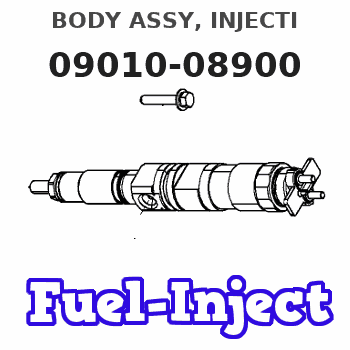
Information body assy, injecti
Rating:
KIT List:
| Body assy, injecti | 1904400360 |
| Body assy, injecti | 1904400360 |
| Body assy, injecti | 1904400360 |
| Body assy, injecti | 1904400360 |
Scheme ###:
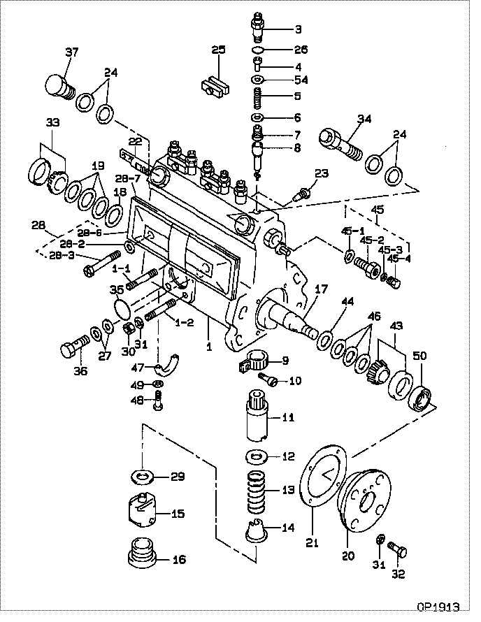
| 000. | [01] | 09010-08900 | BODY ASSY, INJECTI | ME728200 |
| 001. | [01] | 19011-04580 | HOUSING KIT, INJEC | ME728883 |
| 001-001. | [01] | 94904-30010 | BOLT, STUD | ME702091 |
| 001-002. | [02] | 94904-31630 | BOLT, STUD | ME702092 |
| 003. | [06] | 09013-10710 | HOLDER, DELIVERY V | ME702050 |
| 004. | [06] | 09013-30261 | STOPPER, DELIVERY | ME702051 |
| 005. | [06] | 09013-60920 | SPRING, DELIVERY V | ME703729 |
| 006. | [06] | 09013-70100 | GASKET, DELIVERY V | ME702053 |
| 007. | [06] | 09014-02130 | VALVE SUB-ASSY, IN | ME728884 |
| 008. | [06] | 09015-04920 | ELEMENT SUB-ASSY, | ME728885 |
| 009. | [06] | 09015-60010 | PINION, PLUNGER CO | ME702058 |
| 010. | [06] | 09015-70010 | SCREW, PLUNGER CON | ME702059 |
| 011. | [06] | 09016-10330 | SLEEVE, PLUNGER CO | ME702060 |
| 012. | [06] | 09016-30191 | SEAT, SPRING, UPR | ME736080 |
| 012. | [06] | 09016-30010 | SEAT, SPRING, UPR | ME702061 |
| 013. | [06] | 09016-40090 | SPRING, PUMP PLUNG | ME702554 |
| 014. | [06] | 09016-50160 | SEAT, SPRING, LWR | MM514055 |
| 015. | [06] | 09017-00070 | TAPPET SUB-ASSY,IN | ME702556 |
| 016. | [06] | 09018-90090 | PLUG, INJECTION PU | ME703276 |
| 017. | [01] | 09019-10620 | CAMSHAFT, INJECTIO | ME702072 |
| 018. | [01] | 09019-30020 | RING, CAMSHAFT ADJ | ME702074 |
| 019. | [3C] | 09019-40400 | PLATE, CAMSHAFT SH | ME728352 |
| 019. | [3C] | 09019-40290 | PLATE, CAMSHAFT SH | ME703274 |
| 019. | [3C] | 09019-40150 | PLATE, CAMSHAFT SH | ME703273 |
| 019. | [3C] | 09019-40140 | PLATE, CAMSHAFT SH | ME703272 |
| 019. | [3C] | 09019-40110 | PLATE, CAMSHAFT SH | ME703583 |
| 019. | [3C] | 09019-40060 | PLATE, CAMSHAFT SH | ME022103 |
| 019. | [3C] | 09019-40050 | PLATE, CAMSHAFT SH | ME022102 |
| 019. | [3C] | 09019-40040 | PLATE, CAMSHAFT SH | ME022101 |
| 019. | [3C] | 09019-40030 | PLATE, CAMSHAFT SH | ME022100 |
| 019. | [3C] | 09019-40020 | PLATE, CAMSHAFT SH | ME022099 |
| 019. | [3C] | 09019-40010 | PLATE, CAMSHAFT SH | ME702075 |
| 020. | [01] | 09020-10371 | COVER, BEARING | ME702077 |
| 021. | [01] | 09020-60150 | GASKET, BEARING CO | ME728350 |
| 021. | [01] | 09020-60040 | GASKET, BEARING CO | ME702078 |
| 022. | [01] | 09021-20412 | RACK, CONTROL | ME703719 |
| 023. | [01] | 09021-50060 | SCREW, RACK GUIDE | ME728163 |
| 024. | [04] | 09022-20070 | WASHER, FUEL PIPE | ME702217 |
| 025. | [03] | 09023-00050 | PLATE SET, VALVE H | ME702558 |
| 026. | [06] | 94914-02570 | O-RING | ME702098 |
| 027. | [02] | 09025-10010 | WASHER, INJECTION | ME702595 |
| 028. | [01] | 09027-00622 | COVER SUB-ASSY, IN | 09027-00621 |
| 028. | [01] | 09027-00691 | COVER SUB-ASSY, IN | ME702084 |
| 028-002. | [02] | 09024-30030 | PACKING, AIR BLEED | ME702057 |
| 028-003. | [02] | 09027-60030 | SCREW | ME703028 |
| 028-006. | [01] | 09027-50083 | PROCESSING DRAWING | ME702602 |
| 028-007. | [01] | 09027-20220 | GASKET, INJECTION | ME702085 |
| 029. | [6C] | 09031-10100 | PLATE, TAPPET ADJU | MM500308 |
| 029. | [6C] | 09031-10110 | PLATE, TAPPET ADJU | MM500309 |
| 029. | [6C] | 09031-10120 | PLATE, TAPPET ADJU | MM500310 |
| 029. | [6C] | 09031-10130 | PLATE, TAPPET ADJU | MM500311 |
| 029. | [6C] | 09031-10140 | PLATE, TAPPET ADJU | MM500312 |
| 029. | [6C] | 09031-10150 | PLATE, TAPPET ADJU | MM500313 |
| 029. | [6C] | 09031-10290 | PLATE, TAPPET ADJU | ME728060 |
| 029. | [6C] | 09031-10090 | PLATE, TAPPET ADJU | MM500307 |
| 029. | [6C] | 09031-10080 | PLATE, TAPPET ADJU | MM500306 |
| 029. | [6C] | 09031-10010 | PLATE, TAPPET ADJU | ME702559 |
| 029. | [6C] | 09031-10020 | PLATE, TAPPET ADJU | MM500300 |
| 029. | [6C] | 09031-10030 | PLATE, TAPPET ADJU | MM500301 |
| 029. | [6C] | 09031-10040 | PLATE, TAPPET ADJU | MM500302 |
| 029. | [6C] | 09031-10050 | PLATE, TAPPET ADJU | MM500303 |
| 029. | [6C] | 09031-10060 | PLATE, TAPPET ADJU | MM500304 |
| 029. | [6C] | 09031-10070 | PLATE, TAPPET ADJU | MM500305 |
| 030. | [03] | 90160-06051 | NUT, HEXAGON | ME702588 |
| 031. | [07] | 90258-06001 | WASHER, SPRING | ME702596 |
| 032. | [04] | 09152-40330 | SCREW, STOPPER | ME702089 |
| 033. | [01] | 94910-10120 | BEARING, ROLLER | ME702096 |
| 034. | [01] | 09031-00110 | VALVE ASSY, OVERFL | ME702087 |
| 035. | [01] | 94914-00380 | O-RING | ME702097 |
| 036. | [01] | 94918-00060 | SCREW, HOLLOW | ME702598 |
| 037. | [01] | 94918-00310 | SCREW, HOLLOW | ME702236 |
| 043. | [01] | 94910-10071 | BEARING, ROLLER | ME702562 |
| 044. | [01] | 09019-30050 | RING, CAMSHAFT ADJ | ME702073 |
| 045. | [01] | 09024-00010 | BLEEDER SUB-ASSY, | ME702083 |
| 045-001. | [01] | 09024-10010 | WASHER, AIR BLEEDE | ME702102 |
| 045-002. | [01] | 09024-20010 | NIPPLE, AIR BLEEDE | ME022094 |
| 045-003. | [01] | 09024-30030 | PACKING, AIR BLEED | ME702057 |
| 045-004. | [01] | 09024-40010 | SCREW, AIR BLEEDER | MM501930 |
| 046. | [3C] | 09019-40410 | PLATE, CAMSHAFT SH | ME728353 |
| 046. | [3C] | 09019-40360 | PLATE, CAMSHAFT SH | ME703469 |
| 046. | [3C] | 09019-40350 | PLATE, CAMSHAFT SH | ME703468 |
| 046. | [3C] | 09019-40340 | PLATE, CAMSHAFT SH | ME703467 |
| 046. | [3C] | 09019-40170 | PLATE, CAMSHAFT SH | ME703271 |
| 046. | [3C] | 09019-40160 | PLATE, CAMSHAFT SH | ME703270 |
| 046. | [3C] | 09019-40100 | PLATE, CAMSHAFT SH | MM500694 |
| 046. | [3C] | 09019-40090 | PLATE, CAMSHAFT SH | MM500693 |
| 046. | [3C] | 09019-40080 | PLATE, CAMSHAFT SH | MM500692 |
| 046. | [3C] | 09019-40070 | PLATE, CAMSHAFT SH | ME702076 |
| 047. | [01] | 09036-10040 | BEARING, CENTER | ME702088 |
| 048. | [02] | 94900-66550 | SCREW | ME736044 |
| 048. | [02] | 91050-05351 | SCREW, CROSSRECESS | ME702597 |
| 049. | [02] | 94901-81030 | WASHER, COPPER PLA | ME702094 |
| 050. | [01] | 94915-01620 | SEAL, OIL | ME702099 |
| 054. | [6C] | 94901-35140 | WASHER, PLATE, SK | ME703632 |
| 054. | [6C] | 94901-35930 | WASHER, PLATE, SK | ME703514 |
| 054. | [6C] | 90208-04610 | WASHER, PLATE | ME702093 |
| 054. | [6C] | 90218-04620 | WASHER, PLATE | ME703668 |
Include in #3:
Cross reference number
| Part num | Firm num | Firm | Name |
| 09010-08900 | ME728200 | BODY ASSY, INJECTI | |
| ME728200 | MITSUBISHI | BODY ASSY, INJECTI |
Information:
Protection Devices
The Caterpillar generator mounted control panel is equipped with protection devices to protect the engine while cranking.Batteries
Lights or buttons may indicate if a fault has occurred in the battery charging system causing the battery to be either undercharged or overcharged.Overcranking
A timer allows the engine to crank either once for 30 seconds, or to crank through 5 ten-second cranking cycles (depending upon the device used) while unattended. If the engine does not start before the time elapsed, the fuel system will be shutoff and a light will indicate a starting failure. Engine Operation
Prealarm systems provide an audible and/or a visual indication for low oil pressure, high water temperature, low fuel supply or low jacket water temperature before the condition becomes critical. These alarms are self resetting when the condition is corrected. The engine may also be equipped with shutdown devices. If low oil pressure, high jacket water temperature or an engine overspeed condition occurs, the engine will be shutdown and a corresponding button or light will indicate the cause of the shutdown. These devices must be reset after repairs have been made and before starting. See the topic, EMERGENCY SHUTOFF DEVICES AND ALARMS.Generator set control panels should be equipped with an ammeter, a frequency meter and a voltmeter. Depending upon the type of operation, the panel may also be equipped with other meters and lights. Know these instruments and their normal readings. They will indicate how the generator set is performing.Shutting Down
A timer allows the transfer switch to transfer the load to another source and to continue engine running for up to 2 minutes for cooling purposes before stopping.Engine Exerciser
At preset times, the exerciser will start, run and stop the engine in order to ensure both proper lubrication of all engine parts and proper equipment operation if and when the standby unit is needed.Become familiar with all instructions included with the equipment.Woodward Governors
Woodward Governors are usually electrically operated from a control panel.Generator Set Control Panel
The generator set control panel is located on top of the generator and is equipped with the following controls and gauges:Panel lights (1) are controlled by an ON/OFF switch (7). An ammeter (2), frequency meter (3) and a voltmeter (4) show the output of the generator. Two gauges (5 and 6) show engine oil pressure and water temperature respectively. The ammeter selector switch (12) gives the operator a choice of which phase (T1, T2 or T3) of the generator output the ammeter (2) will show. Voltage level rheostat (9) takes the place of the voltage level rheostat in the generator regulator assembly.The engine control switch (8) has four positions; MANUAL, AUTOMATIC, STOP and OFF. Placing