Information body assy, injecti
Rating:
KIT List:
| Body assy, injecti | 1904400300 |
| Body assy, injecti | 1904400300 |
| Body assy, injecti | 1904400300 |
| Body assy, injecti | 1904400300 |
| Body assy, injecti | 1904400300 |
Scheme ###:
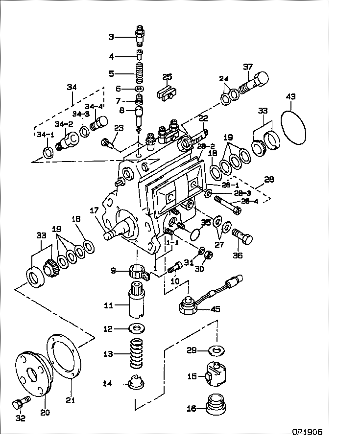
| 000. | [01] | 09010-08680 | BODY ASSY, INJECTI | ME728125 |
| 001. | [01] | 19011-04470 | HOUSING KIT, INJEC | ME728764 |
| 001-001. | [03] | 94904-30010 | BOLT, STUD | ME702091 |
| 003. | [04] | 09013-10010 | HOLDER, DELIVERY V | ME022081 |
| 004. | [04] | 09013-30030 | STOPPER, DELIVERY | ME022082 |
| 005. | [04] | 09013-60200 | SPRING, DELIVERY V | ME022083 |
| 005. | [04] | 09013-61180 | SPRING, DELIVERY V | ME736260 |
| 006. | [04] | 09013-70010 | GASKET, DELIVERY V | ME022084 |
| 007. | [04] | 09014-00021 | VALVE SUB-ASSY, IN | ME022085 |
| 008. | [04] | 09015-03830 | ELEMENT SUB-ASSY, | ME728763 |
| 009. | [04] | 09015-60010 | PINION, PLUNGER CO | ME702058 |
| 010. | [04] | 09015-70010 | SCREW, PLUNGER CON | ME702059 |
| 011. | [04] | 09016-10330 | SLEEVE, PLUNGER CO | ME702060 |
| 012. | [04] | 09016-30010 | SEAT, SPRING, UPR | ME702061 |
| 012. | [04] | 09016-30191 | SEAT, SPRING, UPR | ME736080 |
| 013. | [04] | 09016-40320 | SPRING, PUMP PLUNG | ME728173 |
| 013. | [04] | 09016-40350 | SPRING, PUMP PLUNG | ME736081 |
| 014. | [04] | 09016-50160 | SEAT, SPRING, LWR | MM514055 |
| 015. | [04] | 09017-00070 | TAPPET SUB-ASSY,IN | ME702556 |
| 016. | [03] | 09018-90090 | PLUG, INJECTION PU | ME703276 |
| 017. | [01] | 09019-10082 | CAMSHAFT, INJECTIO | MM500682 |
| 018. | [02] | 09019-30020 | RING, CAMSHAFT ADJ | ME702074 |
| 019. | [6C] | 09019-40400 | PLATE, CAMSHAFT SH | ME728352 |
| 019. | [6C] | 09019-40290 | PLATE, CAMSHAFT SH | ME703274 |
| 019. | [6C] | 09019-40150 | PLATE, CAMSHAFT SH | ME703273 |
| 019. | [6C] | 09019-40140 | PLATE, CAMSHAFT SH | ME703272 |
| 019. | [6C] | 09019-40110 | PLATE, CAMSHAFT SH | ME703583 |
| 019. | [6C] | 09019-40060 | PLATE, CAMSHAFT SH | ME022103 |
| 019. | [6C] | 09019-40050 | PLATE, CAMSHAFT SH | ME022102 |
| 019. | [6C] | 09019-40040 | PLATE, CAMSHAFT SH | ME022101 |
| 019. | [6C] | 09019-40030 | PLATE, CAMSHAFT SH | ME022100 |
| 019. | [6C] | 09019-40020 | PLATE, CAMSHAFT SH | ME022099 |
| 019. | [6C] | 09019-40010 | PLATE, CAMSHAFT SH | ME728352 |
| 020. | [01] | 09020-10521 | COVER, BEARING | ME703050 |
| 021. | [01] | 09020-60010 | GASKET, BEARING CO | ME703584 |
| 021. | [01] | 09020-60160 | GASKET, BEARING CO | ME728820 |
| 022. | [01] | 09021-20020 | RACK, CONTROL | MM500699 |
| 023. | [01] | 09021-50060 | SCREW, RACK GUIDE | ME728163 |
| 024. | [02] | 09022-20070 | WASHER, FUEL PIPE | ME702217 |
| 025. | [02] | 09023-00031 | PLATE SET, VALVE H | ME702082 |
| 027. | [02] | 09025-10010 | WASHER, INJECTION | ME702595 |
| 028. | [01] | 09027-01090 | COVER SUB-ASSY, IN | ME703787 |
| 028. | [01] | 09027-01460 | COVER SUB-ASSY, IN | ME736539 |
| 028-001. | [01] | 09027-50182 | PROCESSING DRAWING | ME703051 |
| 028-002. | [01] | 09027-20210 | GASKET, INJECTION | ME703052 |
| 028-003. | [02] | 09024-30030 | PACKING, AIR BLEED | ME702057 |
| 028-004. | [02] | 09027-60030 | SCREW | ME703028 |
| 029. | [4C] | 09031-10100 | PLATE, TAPPET ADJU | MM500308 |
| 029. | [4C] | 09031-10110 | PLATE, TAPPET ADJU | MM500309 |
| 029. | [4C] | 09031-10120 | PLATE, TAPPET ADJU | MM500310 |
| 029. | [4C] | 09031-10130 | PLATE, TAPPET ADJU | MM500311 |
| 029. | [4C] | 09031-10140 | PLATE, TAPPET ADJU | MM500312 |
| 029. | [4C] | 09031-10150 | PLATE, TAPPET ADJU | MM500313 |
| 029. | [4C] | 09031-10290 | PLATE, TAPPET ADJU | ME728060 |
| 029. | [4C] | 09031-10090 | PLATE, TAPPET ADJU | MM500307 |
| 029. | [4C] | 09031-10080 | PLATE, TAPPET ADJU | MM500306 |
| 029. | [4C] | 09031-10010 | PLATE, TAPPET ADJU | ME702559 |
| 029. | [4C] | 09031-10020 | PLATE, TAPPET ADJU | MM500300 |
| 029. | [4C] | 09031-10030 | PLATE, TAPPET ADJU | MM500301 |
| 029. | [4C] | 09031-10040 | PLATE, TAPPET ADJU | MM500302 |
| 029. | [4C] | 09031-10050 | PLATE, TAPPET ADJU | MM500303 |
| 029. | [4C] | 09031-10060 | PLATE, TAPPET ADJU | MM500304 |
| 029. | [4C] | 09031-10070 | PLATE, TAPPET ADJU | MM500305 |
| 030. | [03] | 90160-06051 | NUT, HEXAGON | ME702588 |
| 031. | [03] | 90258-06001 | WASHER, SPRING | ME702596 |
| 032. | [04] | 91418-06201 | BOLT, W/WASHER | ME702041 |
| 033. | [02] | 94910-10120 | BEARING, ROLLER | ME702096 |
| 034. | [01] | 09024-00010 | BLEEDER SUB-ASSY, | ME702083 |
| 034-001. | [01] | 09024-10010 | WASHER, AIR BLEEDE | ME702102 |
| 034-002. | [01] | 09024-20010 | NIPPLE, AIR BLEEDE | ME022094 |
| 034-003. | [01] | 09024-30030 | PACKING, AIR BLEED | ME702057 |
| 034-004. | [01] | 09024-40010 | SCREW, AIR BLEEDER | MM501930 |
| 035. | [01] | 94914-00380 | O-RING | ME702097 |
| 036. | [01] | 94918-00060 | SCREW, HOLLOW | ME702598 |
| 037. | [01] | 94918-00310 | SCREW, HOLLOW | ME702236 |
| 043. | [01] | 94914-00060 | O-RING | MM500727 |
| 045. | [01] | 07630-00670 | PICKUP ASSY, TACHO | ME016374 |
Include in #3:
Cross reference number
| Part num | Firm num | Firm | Name |
| 09010-08680 | ME728125 | BODY ASSY, INJECTI | |
| ME728125 | MITSUBISHI | BODY ASSY, INJECTI |
Information:
Fuel Flow
Fuel System Schematic
(1) Fuel injection nozzle. (2) Fuel injection lines. (3) Fuel return line. (4) Constant bleed orifice (part of the elbow). (5) Fuel injection pump housing. (6) Fuel priming pump. (7) Check valves. (8) Fuel transfer pump. (9) Fuel tank. (10) Primary fuel filter. (11) Secondary fuel filter.Fuel is pulled from fuel tank (9) through primary fuel filter (10) by fuel transfer pump (8). From the fuel transfer pump the fuel is pushed through secondary fuel filter (11) and to the fuel manifold in fuel injection pump housing (5). Fuel pressure in the fuel manifold is determined by the fuel transfer pump spring. A constant bleed orifice is in the fuel return line elbow. Constant e bleed orifice (4) lets a constant flow of fuel go through fuel return line (3) back to fuel tank (9). This helps keep the fuel cool and free of air. The individual fuel injection pumps get fuel from the fuel manifold and push fuel at a very high pressure through fuel lines (2) to fuel injection nozzles (1). Each fuel injection nozzle has very small holes in the tip that change the flow of fuel to a very fine spray that gives good fuel combustion in the cylinder.Fuel Injection Pump
The fuel injection pump increases the pressure of the fuel and sends an exact amount of fuel to the fuel injection nozzle. There is one fuel injection pump for each cylinder in the engine.
Fuel Injection Pump
(1) Spill port. (2) Check valve. (3) Pump barrel. (4) Bypass port.