Information body assy, injecti
Rating:
KIT List:
| Body assy, injecti | 1904400320 |
| Body assy, injecti | 1904400320 |
Scheme ###:
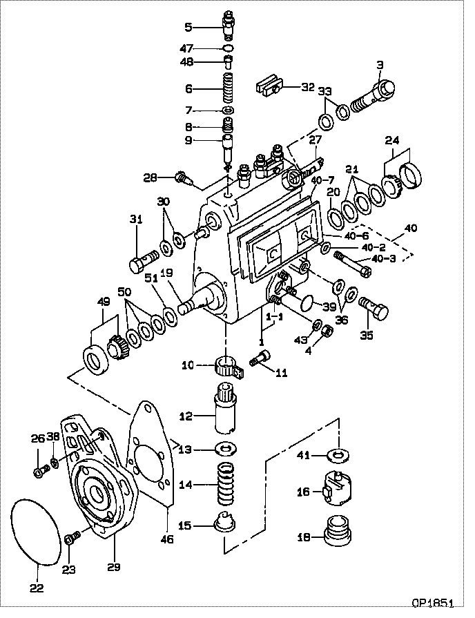
| 000. | [01] | 09010-08020 | BODY ASSY, INJECTI | 22120-56280 |
| 001. | [01] | 19011-03360 | HOUSING KIT, INJEC | 22190-58230 |
| 001-001. | [03] | 94904-30010 | BOLT, STUD | 90099-07071 |
| 003. | [01] | 09031-00130 | VALVE ASSY, OVERFL | 22160-78030 |
| 004. | [03] | 90160-06051 | NUT, HEXAGON | 90092-10101 |
| 005. | [04] | 09013-10320 | HOLDER, DELIVERY V | 22131-78030 |
| 006. | [04] | 09013-60120 | SPRING, DELIVERY V | 22148-78030 |
| 007. | [04] | 09013-70100 | GASKET, DELIVERY V | 22149-78030 |
| 008. | [04] | 09014-01470 | VALVE SUB-ASSY, IN | 22104-58230 |
| 009. | [04] | 09015-04310 | ELEMENT SUB-ASSY, | |
| 010. | [04] | 09015-60010 | PINION, PLUNGER CO | 22155-76010 |
| 011. | [04] | 09015-70010 | SCREW, PLUNGER CON | 22156-76010 |
| 012. | [02] | 09016-10330 | SLEEVE, PLUNGER CO | 22142-58230 |
| 013. | [04] | 09016-30010 | SEAT, SPRING, UPR | 22143-77020 |
| 013. | [04] | 09016-30191 | SEAT, SPRING, UPR | |
| 014. | [04] | 09016-40090 | SPRING, PUMP PLUNG | 22144-46010 |
| 015. | [04] | 09016-50160 | SEAT, SPRING, LWR | 22145-78030 |
| 016. | [04] | 09017-00070 | TAPPET SUB-ASSY,IN | 22106-46010 |
| 018. | [04] | 09018-90090 | PLUG, INJECTION PU | |
| 019. | [01] | 09019-10970 | CAMSHAFT, INJECTIO | 22146-58230 |
| 019. | [01] | 09019-10880 | CAMSHAFT, INJECTIO | |
| 020. | [01] | 09019-30020 | RING, CAMSHAFT ADJ | 22147-77020 |
| 021. | [ C] | 09019-40010 | PLATE, CAMSHAFT SH | 22161-76010 |
| 021. | [ C] | 09019-40290 | PLATE, CAMSHAFT SH | |
| 021. | [ C] | 09019-40170 | PLATE, CAMSHAFT SH | 22166-78037 |
| 021. | [ C] | 09019-40160 | PLATE, CAMSHAFT SH | 22166-78036 |
| 021. | [ C] | 09019-40150 | PLATE, CAMSHAFT SH | 22166-78031 |
| 021. | [ C] | 09019-40140 | PLATE, CAMSHAFT SH | 22166-78030 |
| 021. | [ C] | 09019-40110 | PLATE, CAMSHAFT SH | |
| 021. | [ C] | 09019-40060 | PLATE, CAMSHAFT SH | 22166-76010 |
| 021. | [ C] | 09019-40050 | PLATE, CAMSHAFT SH | 22165-76010 |
| 021. | [ C] | 09019-40040 | PLATE, CAMSHAFT SH | 22164-76010 |
| 021. | [ C] | 09019-40030 | PLATE, CAMSHAFT SH | 22163-76010 |
| 021. | [ C] | 09019-40020 | PLATE, CAMSHAFT SH | 22162-76010 |
| 022. | [01] | 94914-03690 | O-RING | 90099-14079 |
| 023. | [04] | 94900-72471 | SCREW, W/WASHER | 90099-00928 |
| 024. | [01] | 94910-10120 | BEARING, ROLLER | 90099-10087 |
| 026. | [01] | 94900-62961 | SCREW | 90099-00894 |
| 027. | [01] | 09021-20020 | RACK, CONTROL | 22114-36010 |
| 028. | [01] | 09021-50060 | SCREW, RACK GUIDE | 22115-78140 |
| 029. | [01] | 09020-40240 | FLANGE, INJECTION | 22181-58230 |
| 030. | [02] | 09022-20070 | WASHER, FUEL PIPE | 94712-77121 |
| 031. | [01] | 94918-00310 | SCREW, HOLLOW | 90099-18010 |
| 032. | [02] | 09023-00050 | PLATE SET, VALVE H | 22102-58230 |
| 033. | [02] | 09024-10010 | WASHER, AIR BLEEDE | 22119-77020 |
| 035. | [01] | 94918-00680 | SCREW, HOLLOW | 90401-10006 |
| 036. | [02] | 94901-81570 | WASHER, COPPER PLA | 90099-01451 |
| 038. | [01] | 94901-81020 | WASHER, COPPER PLA | 90201-08106 |
| 039. | [01] | 94914-00380 | O-RING | 90099-14015 |
| 040. | [01] | 09027-00961 | COVER SUB-ASSY, IN | |
| 040-002. | [02] | 09024-30030 | PACKING, AIR BLEED | 22121-77020 |
| 040-003. | [02] | 09027-60030 | SCREW | |
| 040-006. | [01] | 09027-50182 | PROCESSING DRAWING | 22563-78050 |
| 040-007. | [01] | 09027-20210 | GASKET, INJECTION | 22153-78030 |
| 041. | [ C] | 09031-10290 | PLATE, TAPPET ADJU | 22186-78030 |
| 041. | [ C] | 09031-10150 | PLATE, TAPPET ADJU | 22186-48010 |
| 041. | [ C] | 09031-10140 | PLATE, TAPPET ADJU | 22186-46010 |
| 041. | [ C] | 09031-10130 | PLATE, TAPPET ADJU | 22185-46010 |
| 041. | [ C] | 09031-10120 | PLATE, TAPPET ADJU | 22184-46010 |
| 041. | [ C] | 09031-10110 | PLATE, TAPPET ADJU | 22183-46010 |
| 041. | [ C] | 09031-10100 | PLATE, TAPPET ADJU | 22182-46010 |
| 041. | [ C] | 09031-10090 | PLATE, TAPPET ADJU | 22189-48036 |
| 041. | [ C] | 09031-10080 | PLATE, TAPPET ADJU | 22189-48035 |
| 041. | [ C] | 09031-10010 | PLATE, TAPPET ADJU | 22187-46010 |
| 041. | [ C] | 09031-10020 | PLATE, TAPPET ADJU | 22188-46010 |
| 041. | [ C] | 09031-10030 | PLATE, TAPPET ADJU | 22189-46010 |
| 041. | [ C] | 09031-10040 | PLATE, TAPPET ADJU | 22189-48031 |
| 041. | [ C] | 09031-10050 | PLATE, TAPPET ADJU | 22189-48032 |
| 041. | [ C] | 09031-10060 | PLATE, TAPPET ADJU | 22189-48033 |
| 041. | [ C] | 09031-10070 | PLATE, TAPPET ADJU | 22189-48034 |
| 043. | [03] | 90258-06001 | WASHER, SPRING | 94511-00600 |
| 046. | [01] | 09020-60080 | GASKET, BEARING CO | 22195-58230 |
| 046. | [01] | 09020-60180 | GASKET, BEARING CO | |
| 047. | [04] | 94914-02570 | O-RING | 90099-14070 |
| 048. | [04] | 09013-30010 | STOPPER, DELIVERY | 22194-78030 |
| 049. | [01] | 94910-10071 | BEARING, ROLLER | 90099-10151 |
| 050. | [ C] | 09019-40360 | PLATE, CAMSHAFT SH | 22166-78144 |
| 050. | [ C] | 09019-40350 | PLATE, CAMSHAFT SH | 22166-78143 |
| 050. | [ C] | 09019-40340 | PLATE, CAMSHAFT SH | 22166-78142 |
| 050. | [ C] | 09019-40100 | PLATE, CAMSHAFT SH | 22166-78035 |
| 050. | [ C] | 09019-40090 | PLATE, CAMSHAFT SH | 22166-78034 |
| 050. | [ C] | 09019-40080 | PLATE, CAMSHAFT SH | 22166-78033 |
| 050. | [ C] | 09019-40070 | PLATE, CAMSHAFT SH | 22166-78032 |
| 051. | [01] | 09019-30050 | RING, CAMSHAFT ADJ | 22147-78030 |
Include in #3:
09010-08020
as BODY ASSY, INJECTI
Cross reference number
| Part num | Firm num | Firm | Name |
| 09010-08020 | 22120-5628 | BODY ASSY, INJECTI | |
| 22120-56280 | TOYOTA | BODY ASSY, INJECTI |
Information:
START BY:a. remove valve coversb. remove rocker shaft assemblies and pushrodsc. remove fuel injection nozzles (earlier)
Be sure that the piston is at Top Center so that the valves will be held in position when the springs are removed.
1. Remove the valve cover bases.2. Remove the valve stem locks with tooling (A) using the following procedure: a. Install adapter plate (1) with two OS1618 (5/16-18 x 1 in.) bolts.b. Install stud (2) and nut (3). Tighten the nut. c. Install plate (4), washer (5) and nut (6). Tighten the nut until the locks are free.d. Remove locks (7), and remove the nut, washer and plate from the stud. Remove the stud and adapter plate from the fuel injection nozzle adapter. 3. Remove rotocoil (8), spring (9) and washer (10). 4. Use tool (B) to remove fuel injection nozzle adapter (11) from the cylinder head assembly. 5. Remove washers (12) and seals (13) from adapters (11).Install Fuel Injection Nozzle Adapters (Earlier)
1. Inspect seals (3) for damage or wear, and make a replacement if necessary.2. Install washers (1) and seals (3) on adapters (2).3. Put liquid soap in the bores of the cylinder head and on the seals of the fuel injection nozzle adapters.4. Put 5P3931 Anti-Seize Compound on the threads of adapter (2), and install the adapters in the cylinder head assembly. 5. Use tool (A), and tighten the adapters to a torque of 205 14 N m (150 10 lb.ft.). 6. Install washers (6), springs (5) and rotocoils (4). 7. Use tool (B), and compress the springs until locks (7) can be installed. Install locks (7) on the valve stems, and remove tool (B).8. Install the valve cover base. Tighten the valve cover base mounting bolts to a torque of 14 3 N m (10 2 lb.ft.).END BY:a. install fuel injection nozzles (earlier)b. install rocker shaft assemblies and push rodsc. install valve covers