Information body assy, injecti
Rating:
KIT List:
| Body assy, injecti | 1904400300 |
| Body assy, injecti | 1904400300 |
| Body assy, injecti | 1904400300 |
| Body assy, injecti | 1904400300 |
| Body assy, injecti | 1904400300 |
| Body assy, injecti | 1904400300 |
| Body assy, injecti | 1904400300 |
| Body assy, injecti | 1904400300 |
| Body assy, injecti | 1904400300 |
Scheme ###:
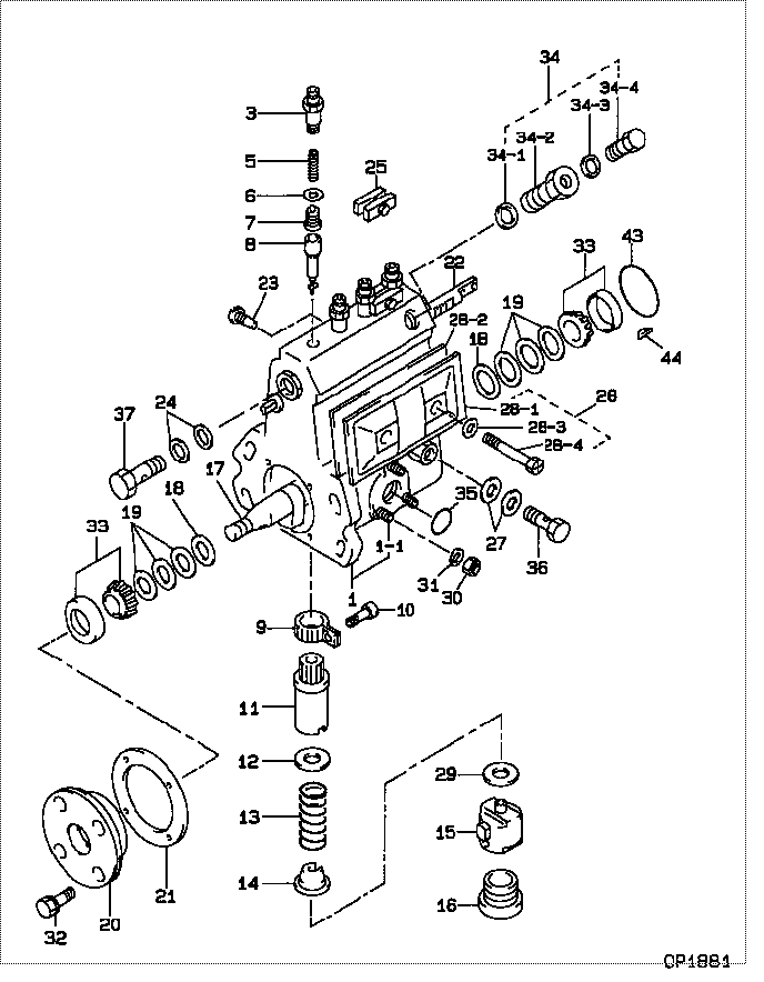
| 000. | [01] | 09010-07820 | BODY ASSY, INJECTI | |
| 001. | [01] | 19011-00963 | HOUSING KIT, INJEC | 19011-00960 |
| 001-001. | [03] | 94904-30010 | BOLT, STUD | 85265-00057 |
| 003. | [04] | 09013-10010 | HOLDER, DELIVERY V | 09013-10010 |
| 005. | [04] | 09013-60040 | SPRING, DELIVERY V | 09013-60040 |
| 006. | [04] | 09013-70010 | GASKET, DELIVERY V | 85265-00019 |
| 007. | [04] | 09014-00960 | VALVE SUB-ASSY, IN | |
| 008. | [04] | 09015-00350 | ELEMENT SUB-ASSY, | 09015-00350 |
| 009. | [04] | 09015-60010 | PINION, PLUNGER CO | 85265-00074 |
| 010. | [04] | 09015-70010 | SCREW, PLUNGER CON | 85265-00027 |
| 011. | [04] | 09016-10330 | SLEEVE, PLUNGER CO | |
| 012. | [04] | 09016-30010 | SEAT, SPRING, UPR | 09016-30010 |
| 012. | [04] | 09016-30191 | SEAT, SPRING, UPR | |
| 013. | [04] | 09016-40090 | SPRING, PUMP PLUNG | 09016-40090 |
| 014. | [04] | 09016-50160 | SEAT, SPRING, LWR | 09016-50160 |
| 015. | [04] | 09017-00070 | TAPPET SUB-ASSY,IN | 09017-00070 |
| 016. | [04] | 09018-90090 | PLUG, INJECTION PU | 09018-90090 |
| 017. | [01] | 09019-10082 | CAMSHAFT, INJECTIO | 09019-10081 |
| 018. | [02] | 09019-30020 | RING, CAMSHAFT ADJ | 09019-30020 |
| 019. | [6C] | 09019-40010 | PLATE, CAMSHAFT SH | 09019-40010 |
| 019. | [6C] | 09019-40020 | PLATE, CAMSHAFT SH | 09019-40020 |
| 019. | [6C] | 09019-40030 | PLATE, CAMSHAFT SH | 09019-40030 |
| 019. | [6C] | 09019-40040 | PLATE, CAMSHAFT SH | 09019-40040 |
| 019. | [6C] | 09019-40050 | PLATE, CAMSHAFT SH | 09019-40050 |
| 019. | [6C] | 09019-40060 | PLATE, CAMSHAFT SH | 09019-40060 |
| 019. | [6C] | 09019-40140 | PLATE, CAMSHAFT SH | |
| 019. | [6C] | 09019-40150 | PLATE, CAMSHAFT SH | |
| 020. | [01] | 09020-10300 | COVER, BEARING | 09020-10300 |
| 021. | [01] | 09020-60010 | GASKET, BEARING CO | 09020-60010 |
| 021. | [01] | 09020-60160 | GASKET, BEARING CO | |
| 022. | [01] | 09021-20020 | RACK, CONTROL | 09021-20020 |
| 023. | [01] | 09021-50060 | SCREW, RACK GUIDE | 09021-50060 |
| 024. | [02] | 09022-20070 | WASHER, FUEL PIPE | 85265-00079 |
| 025. | [02] | 09023-00031 | PLATE SET, VALVE H | 85265-00052 |
| 027. | [02] | 09025-10010 | WASHER, INJECTION | 85265-00077 |
| 028. | [01] | 09027-01460 | COVER SUB-ASSY, IN | |
| 028. | [01] | 09027-01090 | COVER SUB-ASSY, IN | |
| 028-001. | [01] | 09027-50182 | PROCESSING DRAWING | |
| 028-002. | [01] | 09027-20210 | GASKET, INJECTION | |
| 028-003. | [02] | 09024-30030 | PACKING, AIR BLEED | 85265-00016 |
| 028-004. | [02] | 09027-60030 | SCREW | |
| 029. | [4C] | 09031-10100 | PLATE, TAPPET ADJU | 09031-10100 |
| 029. | [4C] | 09031-10110 | PLATE, TAPPET ADJU | 09031-10110 |
| 029. | [4C] | 09031-10120 | PLATE, TAPPET ADJU | 09031-10120 |
| 029. | [4C] | 09031-10130 | PLATE, TAPPET ADJU | 09031-10130 |
| 029. | [4C] | 09031-10140 | PLATE, TAPPET ADJU | 09031-10140 |
| 029. | [4C] | 09031-10150 | PLATE, TAPPET ADJU | 09031-10150 |
| 029. | [4C] | 09031-10090 | PLATE, TAPPET ADJU | 09031-10090 |
| 029. | [4C] | 09031-10080 | PLATE, TAPPET ADJU | 09031-10080 |
| 029. | [4C] | 09031-10070 | PLATE, TAPPET ADJU | 09031-10070 |
| 029. | [4C] | 09031-10010 | PLATE, TAPPET ADJU | 09031-10010 |
| 029. | [4C] | 09031-10020 | PLATE, TAPPET ADJU | 09031-10020 |
| 029. | [4C] | 09031-10030 | PLATE, TAPPET ADJU | 09031-10030 |
| 029. | [4C] | 09031-10040 | PLATE, TAPPET ADJU | 09031-10040 |
| 029. | [4C] | 09031-10050 | PLATE, TAPPET ADJU | 09031-10050 |
| 029. | [4C] | 09031-10060 | PLATE, TAPPET ADJU | 09031-10060 |
| 030. | [03] | 90160-06051 | NUT, HEXAGON | 85265-00085 |
| 031. | [03] | 90258-06001 | WASHER, SPRING | 90258-06001 |
| 032. | [04] | 94904-71360 | BOLT, W/WASHER | 94904-71360 |
| 033. | [02] | 94910-10120 | BEARING, ROLLER | 94910-10121 |
| 034. | [01] | 09024-00010 | BLEEDER SUB-ASSY, | 09024-00010 |
| 034-001. | [01] | 09024-10010 | WASHER, AIR BLEEDE | MM500486 |
| 034-002. | [01] | 09024-20010 | NIPPLE, AIR BLEEDE | 85265-00013 |
| 034-003. | [01] | 09024-30030 | PACKING, AIR BLEED | 85265-00016 |
| 034-004. | [01] | 09024-40010 | SCREW, AIR BLEEDER | 09024-40010 |
| 035. | [01] | 94914-00380 | O-RING | 85265-00084 |
| 036. | [01] | 94918-00060 | SCREW, HOLLOW | 85265-00076 |
| 037. | [01] | 94918-00310 | SCREW, HOLLOW | 85265-00078 |
| 043. | [01] | 94914-00060 | O-RING | 85265-00061 |
| 044. | [01] | 94913-00190 | KEY, WOODRUFF | 94913-00190 |
Include in #3:
09010-07820
as BODY ASSY, INJECTI
Cross reference number
| Part num | Firm num | Firm | Name |
| 09010-07820 | BODY ASSY, INJECTI |
Information:
2. Remove bolts (1) from the adapter. Loosen turbocharger compressor housing clamp (2), and rotate turbocharger tube (3) out of the way of the aftercooler housing. 3. Put identification marks on the bolts which hold the aftercooler cover in position for installation purposes. Remove bolts (4) that hold the aftercooler cover to the aftercooler housing. Remove aftercooler cover (5). 4. Remove four bolts (6), elbow (7), the two adapters and pipe (8). 5. Remove four bolts (9), elbow (10) and two adapters (11). 6. Remove aftercooler core (12) from aftercooler housing (13). 7. Remove O-ring seals (14) and gaskets (15) if necessary.Install Aftercooler Core
1. Clean and inspect all parts. Make a replacement of all parts that are worn or damaged. Lubricate all O-ring seals with clean engine oil at assembly. 2. Install O-ring seals (1). Fasten gaskets (2) to both sides of the aftercooler core flange with 5H2471 Cement. 3. Put aftercooler core (3) in position in the aftercooler housing with the end that has the identification "Jacket Water, Fresh Air" toward the water inlet end of the aftercooler housing. 4. Install cover (4) on the aftercooler housing. Be sure to install the long bolts in the thru bolt holes.
To prevent damage to the aftercooler core, tighten the bolts that hold the aftercooler core before tightening the bolts that hold the adapters.
5. Tighten the aftercooler core cover bolts to a torque of 25 7 N m (18 5 lb.ft.). Tighten the bolts again after engine is operated to a torque of 25 7 N m (18 5 lb.ft.). 6. Install gasket (5) and adapter (6) on the aftercooler housing. 7. Install adapter (7) on adapter (6). 8. Put O-ring seals (8) on pipe (9), and install pipe (9) into elbow (10). 9. Install elbow (11) on pipe (9). Put gasket (12) in position between elbow (11) and adapter (7), and fasten the elbow to aftercooler housing with four bolts. 10. Install gasket (13) and adapter (14) on the aftercooler housing. 11. Install adapter (15) on adapter (14). 12. Put O-ring seal (16) in position on tube (17), and install elbow (18) on tube (17). Put gasket (19) in position between elbow (18) and adapter (15), and fasten the elbow to the aftercooler housing with four bolts. 13. Rotate turbocharger tube (20) into position. Place a gasket between the aftercooler housing and adapter, and install the four bolts and nuts that hold it.14. Tighten turbocharger clamp nut (21) to a torque of 18 3 N m (13 2 lb.ft.). Lightly hit all around the clamp with a soft faced hammer, and tighten the clamp nut again to the same torque value.15. Fill the engine with coolant to the correct level. See the Maintenance Guide.