Information body assy, injecti
Rating:
KIT List:
| Body assy, injecti | 1904400380 |
| Body assy, injecti | 1904400380 |
Scheme ###:
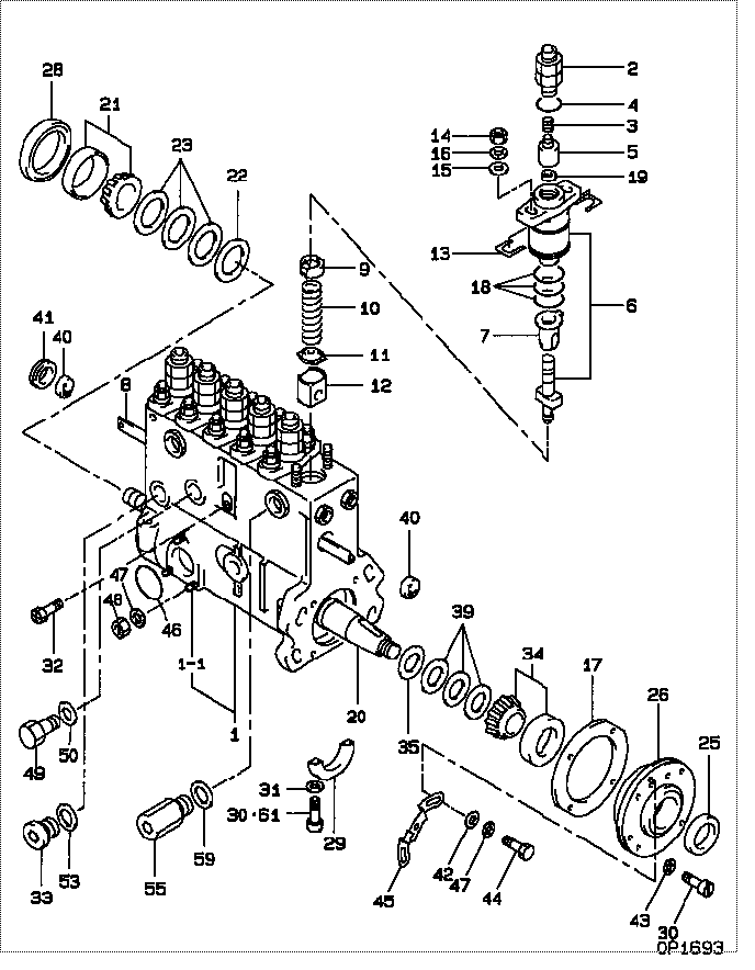
| 000. | [01] | 09010-07740 | BODY ASSY, INJECTI | |
| 001. | [01] | 09011-03850 | HOUSING SUB-ASSY, | |
| 001-001. | [03] | 94904-30010 | BOLT, STUD | |
| 002. | [06] | 09013-00311 | HOLDER SUB-ASSY, D | |
| 003. | [06] | 09013-60730 | SPRING, DELIVERY V | |
| 004. | [06] | 94914-02570 | O-RING | |
| 005. | [06] | 09014-01980 | VALVE SUB-ASSY, IN | |
| 006. | [06] | 09015-04200 | ELEMENT SUB-ASSY, | |
| 007. | [06] | 09016-00150 | SLEEVE SUB-ASSY, C | |
| 008. | [01] | 09021-20700 | RACK, CONTROL | |
| 009. | [06] | 09016-30160 | SEAT, SPRING, UPR | |
| 010. | [06] | 09016-40250 | SPRING, PUMP PLUNG | |
| 011. | [06] | 09016-50150 | SEAT, SPRING, LWR | |
| 012. | [06] | 09017-00320 | TAPPET SUB-ASSY,IN | |
| 013. | [ C] | 09043-80631 | SHIM, ELEMENT HOLD | |
| 013. | [ C] | 09043-80871 | SHIM, ELEMENT HOLD | |
| 013. | [ C] | 09043-80881 | SHIM, ELEMENT HOLD | |
| 013. | [ C] | 09043-80891 | SHIM, ELEMENT HOLD | |
| 013. | [ C] | 09043-80901 | SHIM, ELEMENT HOLD | |
| 013. | [ C] | 09043-80911 | SHIM, ELEMENT HOLD | |
| 013. | [ C] | 09043-80621 | SHIM, ELEMENT HOLD | |
| 013. | [ C] | 09043-80451 | SHIM, ELEMENT HOLD | |
| 013. | [ C] | 09043-80391 | SHIM, ELEMENT HOLD | |
| 013. | [ C] | 09043-80401 | SHIM, ELEMENT HOLD | |
| 013. | [ C] | 09043-80411 | SHIM, ELEMENT HOLD | |
| 013. | [ C] | 09043-80421 | SHIM, ELEMENT HOLD | |
| 013. | [ C] | 09043-80431 | SHIM, ELEMENT HOLD | |
| 013. | [ C] | 09043-80441 | SHIM, ELEMENT HOLD | |
| 014. | [12] | 90196-08651 | NUT, HEXAGON | |
| 015. | [12] | 94901-35880 | WASHER, PLATE, SK | |
| 016. | [12] | 90258-08001 | WASHER, SPRING | |
| 017. | [01] | 09020-60250 | GASKET, BEARING CO | |
| 017. | [01] | 09020-60120 | GASKET, BEARING CO | |
| 018. | [18] | 09013-90020 | O-RING | |
| 019. | [06] | 94901-81730 | WASHER, COPPER PLA | |
| 020. | [01] | 09019-11120 | CAMSHAFT, INJECTIO | |
| 021. | [01] | 94910-10140 | BEARING, ROLLER | |
| 022. | [01] | 09019-30050 | RING, CAMSHAFT ADJ | |
| 023. | [ C] | 09019-40410 | PLATE, CAMSHAFT SH | |
| 023. | [ C] | 09019-40360 | PLATE, CAMSHAFT SH | |
| 023. | [ C] | 09019-40350 | PLATE, CAMSHAFT SH | |
| 023. | [ C] | 09019-40340 | PLATE, CAMSHAFT SH | |
| 023. | [ C] | 09019-40100 | PLATE, CAMSHAFT SH | |
| 023. | [ C] | 09019-40090 | PLATE, CAMSHAFT SH | |
| 023. | [ C] | 09019-40080 | PLATE, CAMSHAFT SH | |
| 023. | [ C] | 09019-40070 | PLATE, CAMSHAFT SH | |
| 025. | [01] | 94915-02820 | SEAL, OIL | |
| 025. | [01] | 94915-01420 | SEAL, OIL | |
| 026. | [01] | 09020-10710 | COVER, BEARING | |
| 028. | [01] | 09043-30020 | RETAINER, BEARING | |
| 029. | [01] | 09036-10180 | BEARING, CENTER | |
| 030. | [04] | 94900-66510 | SCREW | |
| 030. | [06] | 94900-66510 | SCREW | |
| 030. | [06] | 90015-06181 | SCREW, SLOTTED OVA | |
| 031. | [02] | 09024-80010 | WASHER, DRAIN SCRE | |
| 032. | [01] | 09021-50060 | SCREW, RACK GUIDE | |
| 033. | [01] | 09031-70140 | PLUG, SCREW | |
| 034. | [01] | 94910-10130 | BEARING, ROLLER | |
| 035. | [01] | 09019-30060 | RING, CAMSHAFT ADJ | |
| 039. | [ C] | 09019-40420 | PLATE, CAMSHAFT SH | |
| 039. | [ C] | 09019-40390 | PLATE, CAMSHAFT SH | |
| 039. | [ C] | 09019-40380 | PLATE, CAMSHAFT SH | |
| 039. | [ C] | 09019-40370 | PLATE, CAMSHAFT SH | |
| 039. | [ C] | 09019-40330 | PLATE, CAMSHAFT SH | |
| 039. | [ C] | 09019-40320 | PLATE, CAMSHAFT SH | |
| 039. | [ C] | 09019-40310 | PLATE, CAMSHAFT SH | |
| 039. | [ C] | 09019-40300 | PLATE, CAMSHAFT SH | |
| 040. | [02] | 09011-40110 | BUSHING, CONTROL R | |
| 041. | [01] | 09036-70040 | BUSHING, CONTROL R | |
| 042. | [02] | 90200-06241 | WASHER, PLATE | |
| 043. | [04] | 94901-50740 | WASHER, SPRING | |
| 044. | [02] | 90107-06101 | BOLT, HEXAGON | |
| 045. | [01] | 09010-80070 | NEEDLE SUB-ASSY, T | |
| 046. | [01] | 94914-00380 | O-RING | |
| 047. | [05] | 90258-06001 | WASHER, SPRING | |
| 048. | [03] | 90160-06051 | NUT, HEXAGON | |
| 049. | [01] | 09116-70031 | PLUG, SCREW | |
| 050. | [01] | 09024-10010 | WASHER, AIR BLEEDE | |
| 053. | [01] | 94901-80350 | WASHER, COPPER PLA | |
| 055. | [01] | 09031-00160 | VALVE ASSY, OVERFL | |
| 059. | [01] | 94901-80550 | WASHER, COPPER PLA | |
| 061. | [02] | 94900-67300 | SCREW |
Include in #3:
09010-07740
as BODY ASSY, INJECTI
Cross reference number
| Part num | Firm num | Firm | Name |
| 09010-07740 | BODY ASSY, INJECTI |
Information:
1. Remove oil supply tube (1) from the turbocharger and oil filter base. 2. Remove four bolts (2), and remove oil drain tube (3) and elbow (4) from the turbocharger. Separate the elbow from the drain tube. Remove the O-ring seal from the tube. 3. The weight of the turbocharger is 24 kg (53 lb.). Fasten a nylon strap and a hoist to the turbocharger, and remove the four bolts and nuts that hold it to the exhaust manifold. Remove turbocharger (5) from exhaust manifold.Install Turbocharger (TV72 & TV78)
1. Inspect all gaskets and O-ring seals for damage, and make a replacement if needed. 2. Put clean engine oil on O-ring seals (1). Connect turbocharger (2) to the inlet pipe, and put it in position on the exhaust manifold.3. Install gasket (3) between the turbocharger and exhaust manifold. Put 5P3931 Anti-Seize Compound on the threads of the bolts, and install the bolts and nuts that hold the turbocharger to the exhaust manifold. Tighten the bolts to a torque of 55 5 N m (41 4 lb.ft.). 4. Put clean engine oil on the O-ring seal, and assemble elbow (4) to drain tube (5).5. Put the gaskets in position on the block and on the turbocharger, and install the drain tube assembly. 6. Put a gasket in position between oil supply tube (6) and the turbocharger. Install oil supply tube (6).Disassemble Turbocharger (TV72 & TV78)
START BY:a. remove turbocharger (TV72 & TV78) 1. Install the turbocharger in tool group (A). Put alignment marks on the three housings of the turbocharger for correct installation and alignment at assembly. Remove "V" clamp (2) and compressor housing (1). 2. Remove "V" clamp (3). Remove cartridge housing (5) from turbine housing (4).
When the nut is loosened, do not put a side force on the shaft. This can result in a bent shaft.
3. Install tool (C) in tool (B), and put the cartridge assembly in tool (C) as shown. Use tool (D) to remove the nut that holds compressor wheel (6). 4. Put the cartridge assembly in tool (E), and use a press (if necessary) to remove compressor wheel (6) from the turbine wheel and shaft assembly. Do not let the turbine wheel and shaft assembly fall during removal of the compressor wheel from the turbine wheel and shaft. 5. Remove seal ring (7) and shroud (8) from turbine wheel and shaft assembly (9). 6. Bend the tabs of the locks from bolts (10), and remove the bolts and locks.7. Remove backplate assembly (11) from the cartridge housing. 8. Remove spacer (12) from backplate assembly (11). Remove seal rings (13) from spacer (12). 9. Remove collar (14), thrust bearing (15) and O-ring seal (16) from the cartridge housing. 10. Remove top bearing (17) and the washer from the cartridge housing. Put a long dye mark on the top face of bearing (17).11. Use tool (F), and remove the two rings that hold the top and bottom bearings in position. Remove the bottom bearing and