Information body assy, injecti
Rating:
KIT List:
| Body assy, injecti | 1904400320 |
| Body assy, injecti | 1904400320 |
Scheme ###:
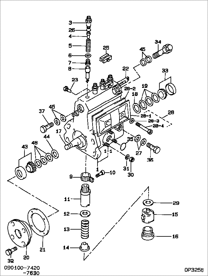
| 000. | [01] | 09010-07420 | BODY ASSY, INJECTI | ME703443 |
| 001. | [01] | 19011-04010 | HOUSING KIT, INJEC | ME703464 |
| 001-001. | [03] | 94904-30010 | BOLT, STUD | ME702091 |
| 003. | [04] | 09013-10710 | HOLDER, DELIVERY V | ME702050 |
| 004. | [04] | 09013-30261 | STOPPER, DELIVERY | ME702051 |
| 005. | [04] | 09013-60800 | SPRING, DELIVERY V | ME702573 |
| 006. | [04] | 09013-70100 | GASKET, DELIVERY V | ME702053 |
| 007. | [04] | 09014-01910 | VALVE SUB-ASSY, IN | ME703465 |
| 008. | [04] | 09015-03050 | ELEMENT SUB-ASSY, | ME703057 |
| 009. | [04] | 09015-60010 | PINION, PLUNGER CO | ME702058 |
| 010. | [04] | 09015-70010 | SCREW, PLUNGER CON | ME702059 |
| 011. | [04] | 09016-10330 | SLEEVE, PLUNGER CO | ME702060 |
| 012. | [04] | 09016-30010 | SEAT, SPRING, UPR | ME702061 |
| 012. | [04] | 09016-30191 | SEAT, SPRING, UPR | ME736080 |
| 013. | [04] | 09016-40090 | SPRING, PUMP PLUNG | ME702554 |
| 014. | [04] | 09016-50160 | SEAT, SPRING, LWR | ME702555 |
| 015. | [04] | 09017-00070 | TAPPET SUB-ASSY,IN | ME702556 |
| 016. | [04] | 09018-90090 | PLUG, INJECTION PU | ME703276 |
| 017. | [01] | 09019-11020 | CAMSHAFT, INJECTIO | ME703058 |
| 018. | [01] | 09019-30020 | RING, CAMSHAFT ADJ | ME702074 |
| 019. | [3C] | 09019-40010 | PLATE, CAMSHAFT SH | ME702075 |
| 019. | [3C] | 09019-40400 | PLATE, CAMSHAFT SH | ME728352 |
| 019. | [3C] | 09019-40110 | PLATE, CAMSHAFT SH | 09019-40110 |
| 019. | [3C] | 09019-40060 | PLATE, CAMSHAFT SH | ME022103 |
| 019. | [3C] | 09019-40050 | PLATE, CAMSHAFT SH | ME022102 |
| 019. | [3C] | 09019-40040 | PLATE, CAMSHAFT SH | ME022101 |
| 019. | [3C] | 09019-40030 | PLATE, CAMSHAFT SH | ME022100 |
| 019. | [3C] | 09019-40020 | PLATE, CAMSHAFT SH | ME022099 |
| 020. | [01] | 09020-10351 | COVER, BEARING | ME703059 |
| 021. | [01] | 09020-60150 | GASKET, BEARING CO | ME728350 |
| 021. | [01] | 09020-60040 | GASKET, BEARING CO | ME702078 |
| 022. | [01] | 09021-20110 | RACK, CONTROL | ME703063 |
| 023. | [01] | 09021-50011 | SCREW, RACK GUIDE | ME702080 |
| 023. | [01] | 09021-50060 | SCREW, RACK GUIDE | ME728163 |
| 025. | [02] | 09023-00050 | PLATE SET, VALVE H | ME702558 |
| 026. | [04] | 94914-02570 | O-RING | ME702098 |
| 027. | [02] | 09025-10010 | WASHER, INJECTION | ME702595 |
| 028. | [01] | 09027-01460 | COVER SUB-ASSY, IN | ME736539 |
| 028. | [01] | 09027-01200 | COVER SUB-ASSY, IN | ME703732 |
| 028. | [01] | 09027-00961 | COVER SUB-ASSY, IN | ME703466 |
| 028-001. | [01] | 09027-50182 | PROCESSING DRAWING | ME703051 |
| 028-002. | [01] | 09027-20210 | GASKET, INJECTION | ME703052 |
| 028-003. | [02] | 09024-30030 | PACKING, AIR BLEED | ME702057 |
| 028-004. | [02] | 09027-60030 | SCREW | ME703028 |
| 029. | [4C] | 09031-10100 | PLATE, TAPPET ADJU | MM500308 |
| 029. | [4C] | 09031-10110 | PLATE, TAPPET ADJU | MM500309 |
| 029. | [4C] | 09031-10120 | PLATE, TAPPET ADJU | MM500310 |
| 029. | [4C] | 09031-10130 | PLATE, TAPPET ADJU | MM500311 |
| 029. | [4C] | 09031-10140 | PLATE, TAPPET ADJU | MM500312 |
| 029. | [4C] | 09031-10150 | PLATE, TAPPET ADJU | MM500313 |
| 029. | [4C] | 09031-10090 | PLATE, TAPPET ADJU | MM500307 |
| 029. | [4C] | 09031-10080 | PLATE, TAPPET ADJU | MM500306 |
| 029. | [4C] | 09031-10070 | PLATE, TAPPET ADJU | MM500305 |
| 029. | [4C] | 09031-10010 | PLATE, TAPPET ADJU | ME702559 |
| 029. | [4C] | 09031-10020 | PLATE, TAPPET ADJU | MM500300 |
| 029. | [4C] | 09031-10030 | PLATE, TAPPET ADJU | MM500301 |
| 029. | [4C] | 09031-10040 | PLATE, TAPPET ADJU | MM500302 |
| 029. | [4C] | 09031-10050 | PLATE, TAPPET ADJU | MM500303 |
| 029. | [4C] | 09031-10060 | PLATE, TAPPET ADJU | MM500304 |
| 030. | [04] | 90160-01601 | NUT, HEXAGON | |
| 031. | [04] | 90258-06001 | WASHER, SPRING | ME702596 |
| 032. | [04] | 91418-06201 | BOLT, W/WASHER | ME702041 |
| 033. | [01] | 94910-10120 | BEARING, ROLLER | ME702096 |
| 034. | [01] | 09031-00110 | VALVE ASSY, OVERFL | ME702087 |
| 035. | [01] | 94914-00380 | O-RING | ME702097 |
| 036. | [01] | 94918-00060 | SCREW, HOLLOW | ME702598 |
| 037. | [01] | 94918-00310 | SCREW, HOLLOW | ME702236 |
| 043. | [01] | 94910-10071 | BEARING, ROLLER | ME702562 |
| 044. | [01] | 09019-30050 | RING, CAMSHAFT ADJ | ME702073 |
| 045. | [04] | 09022-20070 | WASHER, FUEL PIPE | ME702217 |
| 048. | [3C] | 09019-40360 | PLATE, CAMSHAFT SH | ME703469 |
| 048. | [3C] | 09019-40350 | PLATE, CAMSHAFT SH | ME703468 |
| 048. | [3C] | 09019-40340 | PLATE, CAMSHAFT SH | ME703467 |
| 048. | [3C] | 09019-40100 | PLATE, CAMSHAFT SH | MM500694 |
| 048. | [3C] | 09019-40090 | PLATE, CAMSHAFT SH | 09019-40090 |
| 048. | [3C] | 09019-40080 | PLATE, CAMSHAFT SH | MM500692 |
| 048. | [3C] | 09019-40070 | PLATE, CAMSHAFT SH | ME702076 |
| 048. | [3C] | 09019-40410 | PLATE, CAMSHAFT SH | ME728353 |
Include in #3:
09010-07420
as BODY ASSY, INJECTI
Cross reference number
| Part num | Firm num | Firm | Name |
| 09010-07420 | ME703443 | BODY ASSY, INJECTI | |
| ME703443 | MITSUBISHI | BODY ASSY, INJECTI |
Information:
(5) Height of camshaft lobes.To find lobe height, use the procedure that follows:A. Measure camshaft lobe height (5).B. Measure base circle (7).C. Subtract base circle (STEP B) from lobe height (STEP A). The difference is actual lobe lift (6).D. Specified camshaft lobe lift (6) is:4W2430 Camshaft Assembly
a. Exhaust lobe ... 10.211 mm (.4020 in)b. Intake lobe ... 10.211 mm (.4020 in)7W3797 Camshaft Assembly
a. Exhaust lobe ... 10.210 mm (.4020 in)b. Intake lobe ... 10.212 mm (.4021 in)Maximum permissible difference between actual lobe lift (STEP C) and specified lobe lift (STEP D) is 0.13 mm (.005 in).Intake Valve Timing
1. Check the No. 1 intake valve clearance with the engine stopped. The valve clearance must be 0.30 to 0.46 mm (.012 to .018 in). If the valve clearance is not in this range, adjust the clearance to 0.38 mm (.015 in).2. Mark Top Center Position of the crankshaft on the vibration damper or pulley.3. Use a dial indicator to measure the intake valve movement.4. Rotate the crankshaft in the direction of normal engine rotation. Stop when the intake valve is 1.91 mm (.075 in) off its seat in the opening sequence.At this point the crankshaft Top Center Position Mark must be in position as follows: Engines with the 4W2430 Camshaft Assembly ... 7 2° After Top CenterEngines with the 7W3797 Camshaft Assembly ... 1 2° After Top CenterChecking Valve-Camshaft Timing (field procedure)
The following factory procedure as described in the December 11, 1989 Service Magazine article will simplify in the field checking of the camshaft timing procedures.1. Set the No. 3 intake bridge adjustment.2. Set the No. 3 intake valve clearance.3. Install the bolt in the flywheel with No. 1 piston at top center.4. Install the dial indicator (magnetic base) to No. 3 intake bridge.5. Remove the bolt from the flywheel.6. Set the gauge at zero and rotate the engine in the normal direction of operation (counterclockwise as seen from the flywheel end) until dial travel stops.The following chart indicates the correct setting.