Information body assy, injecti
Rating:
KIT List:
| Body assy, injecti | 1904400300 |
| Body assy, injecti | 1904400300 |
| Body assy, injecti | 1904400300 |
| Body assy, injecti | 1904400300 |
| Body assy, injecti | 1904400300 |
| Body assy, injecti | 1904400300 |
| Body assy, injecti | 1904400300 |
| Body assy, injecti | 1904400300 |
| Body assy, injecti | 1904400300 |
| Body assy, injecti | 1904400300 |
| Body assy, injecti | 1904400300 |
| Body assy, injecti | 1904400300 |
| Body assy, injecti | 1904400300 |
| Body assy, injecti | 1904400300 |
| Body assy, injecti | 1904400300 |
Scheme ###:
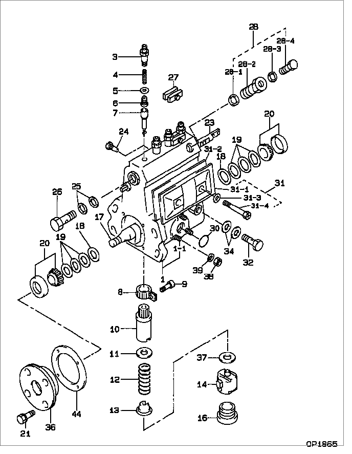
| 000. | [01] | 09010-06870 | BODY ASSY, INJECTI | |
| 001. | [01] | 19011-03121 | HOUSING KIT, INJEC | |
| 001-001. | [03] | 94904-30010 | BOLT, STUD | 85265-00057 |
| 003. | [04] | 09013-10540 | HOLDER, DELIVERY V | |
| 004. | [04] | 09013-60040 | SPRING, DELIVERY V | 09013-60040 |
| 005. | [04] | 09013-70010 | GASKET, DELIVERY V | 85265-00019 |
| 006. | [04] | 09014-00010 | VALVE SUB-ASSY, IN | 09014-00010 |
| 007. | [04] | 09015-00050 | ELEMENT SUB-ASSY, | 09015-00050 |
| 008. | [04] | 09015-60010 | PINION, PLUNGER CO | 85265-00074 |
| 009. | [04] | 09015-70010 | SCREW, PLUNGER CON | 85265-00027 |
| 010. | [04] | 09016-10160 | SLEEVE, PLUNGER CO | 85265-00073 |
| 010. | [04] | 09016-10330 | SLEEVE, PLUNGER CO | |
| 011. | [04] | 09016-30010 | SEAT, SPRING, UPR | 09016-30010 |
| 011. | [04] | 09016-30191 | SEAT, SPRING, UPR | |
| 012. | [04] | 09016-40090 | SPRING, PUMP PLUNG | 09016-40090 |
| 013. | [04] | 09016-50160 | SEAT, SPRING, LWR | 09016-50160 |
| 014. | [04] | 09017-00070 | TAPPET SUB-ASSY,IN | 09017-00070 |
| 016. | [04] | 09018-90090 | PLUG, INJECTION PU | 09018-90090 |
| 017. | [01] | 09019-10082 | CAMSHAFT, INJECTIO | 09019-10081 |
| 018. | [02] | 09019-30020 | RING, CAMSHAFT ADJ | 09019-30020 |
| 019. | [6C] | 09019-40290 | PLATE, CAMSHAFT SH | |
| 019. | [6C] | 09019-40150 | PLATE, CAMSHAFT SH | |
| 019. | [6C] | 09019-40140 | PLATE, CAMSHAFT SH | |
| 019. | [6C] | 09019-40110 | PLATE, CAMSHAFT SH | 09019-40110 |
| 019. | [6C] | 09019-40060 | PLATE, CAMSHAFT SH | 09019-40060 |
| 019. | [6C] | 09019-40050 | PLATE, CAMSHAFT SH | 09019-40050 |
| 019. | [6C] | 09019-40040 | PLATE, CAMSHAFT SH | 09019-40040 |
| 019. | [6C] | 09019-40030 | PLATE, CAMSHAFT SH | 09019-40030 |
| 019. | [6C] | 09019-40020 | PLATE, CAMSHAFT SH | 09019-40020 |
| 019. | [6C] | 09019-40010 | PLATE, CAMSHAFT SH | 09019-40010 |
| 020. | [02] | 94910-10120 | BEARING, ROLLER | 94910-10121 |
| 021. | [04] | 94904-71360 | BOLT, W/WASHER | 94904-71360 |
| 023. | [01] | 09021-20020 | RACK, CONTROL | 09021-20020 |
| 024. | [01] | 09021-50011 | SCREW, RACK GUIDE | 09021-50011 |
| 024. | [01] | 09021-50060 | SCREW, RACK GUIDE | 09021-50060 |
| 025. | [02] | 09022-20070 | WASHER, FUEL PIPE | 85265-00079 |
| 026. | [01] | 94918-00310 | SCREW, HOLLOW | 85265-00078 |
| 027. | [02] | 09023-00031 | PLATE SET, VALVE H | 85265-00052 |
| 028. | [01] | 09024-00010 | BLEEDER SUB-ASSY, | 09024-00010 |
| 028-001. | [01] | 09024-10010 | WASHER, AIR BLEEDE | MM500486 |
| 028-002. | [01] | 09024-20010 | NIPPLE, AIR BLEEDE | 85265-00013 |
| 028-003. | [01] | 09024-30030 | PACKING, AIR BLEED | 85265-00016 |
| 028-004. | [01] | 09024-40010 | SCREW, AIR BLEEDER | 09024-40010 |
| 030. | [01] | 94914-00380 | O-RING | 85265-00084 |
| 031. | [01] | 09027-01090 | COVER SUB-ASSY, IN | |
| 031. | [01] | 09027-01460 | COVER SUB-ASSY, IN | |
| 031-001. | [01] | 09027-50182 | PROCESSING DRAWING | |
| 031-002. | [01] | 09027-20210 | GASKET, INJECTION | |
| 031-003. | [02] | 09024-30030 | PACKING, AIR BLEED | 85265-00016 |
| 031-004. | [02] | 09027-60030 | SCREW | |
| 032. | [01] | 94918-00060 | SCREW, HOLLOW | 85265-00076 |
| 033. | [03] | 90160-06051 | NUT, HEXAGON | 85265-00085 |
| 034. | [02] | 09025-10010 | WASHER, INJECTION | 85265-00077 |
| 035. | [03] | 90258-06001 | WASHER, SPRING | 90258-06001 |
| 036. | [01] | 09020-10300 | COVER, BEARING | 09020-10300 |
| 037. | [4C] | 09031-10100 | PLATE, TAPPET ADJU | 09031-10100 |
| 037. | [4C] | 09031-10110 | PLATE, TAPPET ADJU | 09031-10110 |
| 037. | [4C] | 09031-10120 | PLATE, TAPPET ADJU | 09031-10120 |
| 037. | [4C] | 09031-10130 | PLATE, TAPPET ADJU | 09031-10130 |
| 037. | [4C] | 09031-10140 | PLATE, TAPPET ADJU | 09031-10140 |
| 037. | [4C] | 09031-10150 | PLATE, TAPPET ADJU | 09031-10150 |
| 037. | [4C] | 09031-10290 | PLATE, TAPPET ADJU | |
| 037. | [4C] | 09031-10090 | PLATE, TAPPET ADJU | 09031-10090 |
| 037. | [4C] | 09031-10080 | PLATE, TAPPET ADJU | 09031-10080 |
| 037. | [4C] | 09031-10010 | PLATE, TAPPET ADJU | 09031-10010 |
| 037. | [4C] | 09031-10020 | PLATE, TAPPET ADJU | 09031-10020 |
| 037. | [4C] | 09031-10030 | PLATE, TAPPET ADJU | 09031-10030 |
| 037. | [4C] | 09031-10040 | PLATE, TAPPET ADJU | 09031-10040 |
| 037. | [4C] | 09031-10050 | PLATE, TAPPET ADJU | 09031-10050 |
| 037. | [4C] | 09031-10060 | PLATE, TAPPET ADJU | 09031-10060 |
| 037. | [4C] | 09031-10070 | PLATE, TAPPET ADJU | 09031-10070 |
| 044. | [01] | 09020-60010 | GASKET, BEARING CO | 09020-60010 |
| 044. | [01] | 09020-60160 | GASKET, BEARING CO |
Include in #3:
09010-06870
as BODY ASSY, INJECTI
Cross reference number
| Part num | Firm num | Firm | Name |
| 09010-06870 | BODY ASSY, INJECTI |
Information:
preparatory steps: a) remove rocker shaft assemblyb) remove water temperature regulator1. Disconnect the fuel ratio control sensing line (1). Remove the sensing line clamp bolt (2). 2. Disconnect the turbocharger oil supply line (3) and the oil drain line (4).3. Remove the fuel injection lines (5) and install protective caps.4. Disconnect the air compressor water return line (8). 5. Remove the retaining bolts (7) and the fan drive mounting bracket (6).6. Remove the cylinder head retaining bolts. Attach a hoist and remove the cylinder head assembly-weight 240 lbs. (109,1 kg).Install Cylinder Head Assembly
1. Thoroughly clean the sealing surfaces of the cylinder head and cylinder block. Position a new head gasket on the engine and install the cylinder head assembly.2. Install the push rods and rocker shaft assembly.3. Coat the threads of the cylinder head retaining bolts with 4S9416 Anti-Seize Compound. Install bolts and washers, and tighten them in the following sequence: 1 - Tighten all numbered bolts in numerical order to 115 lb. ft. (15,9 mkg).2 - Retighten all numbered bolts in numerical order to 175 5 lb. ft. (24,2 0,7 mkg).3 - Finally, retighten all numbered bolts (hand torque only) in numerical order to 175 5 lb. ft. (24,2 0,7 mkg).4 - Tighten all lettered bolts in alphabetical order to 22 lb. ft. (3,0 mkg).5 - Retighten all lettered bolts in alphabetical order to 32 5 lb. ft. (4,4 0,7 mkg).6 - Finally, retighten all lettered bolts (hand torque only) in alphabetical order to 32 5 lb. ft. (4,4 0,7 mkg).4. Adjust the inlet and exhaust valve clearance as covered in INSTALL ROCKER SHAFT ASSEMBLY AND PUSH RODS.5. Connect the air compressor water return line.6. Install the fuel lines and tighten the retaining nuts to 30 5 lb. ft. (4,1 0,7 mkg).7. Connect the turbocharger oil supply line and the oil drain line.8. Connect the fuel ratio control sensing line and install the sensing line clamp bolt.9. Install the fan drive mounting bracket and retaining bolts.concluding steps: a) install water temperature regulatorb) install valve cover
1. Thoroughly clean the sealing surfaces of the cylinder head and cylinder block. Position a new head gasket on the engine and install the cylinder head assembly.2. Install the push rods and rocker shaft assembly.3. Coat the threads of the cylinder head retaining bolts with 4S9416 Anti-Seize Compound. Install bolts and washers, and tighten them in the following sequence: 1 - Tighten all numbered bolts in numerical order to 115 lb. ft. (15,9 mkg).2 - Retighten all numbered bolts in numerical order to 175 5 lb. ft. (24,2 0,7 mkg).3 - Finally, retighten all numbered bolts (hand torque only) in numerical order to 175 5 lb. ft. (24,2 0,7 mkg).4 - Tighten all lettered bolts in alphabetical order to 22 lb. ft. (3,0 mkg).5 - Retighten all lettered bolts in alphabetical order to 32 5 lb. ft. (4,4 0,7 mkg).6 - Finally, retighten all lettered bolts (hand torque only) in alphabetical order to 32 5 lb. ft. (4,4 0,7 mkg).4. Adjust the inlet and exhaust valve clearance as covered in INSTALL ROCKER SHAFT ASSEMBLY AND PUSH RODS.5. Connect the air compressor water return line.6. Install the fuel lines and tighten the retaining nuts to 30 5 lb. ft. (4,1 0,7 mkg).7. Connect the turbocharger oil supply line and the oil drain line.8. Connect the fuel ratio control sensing line and install the sensing line clamp bolt.9. Install the fan drive mounting bracket and retaining bolts.concluding steps: a) install water temperature regulatorb) install valve cover