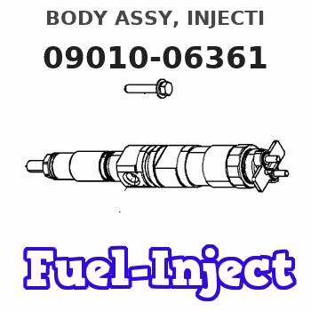
Information body assy, injecti
Rating:
Scheme ###:
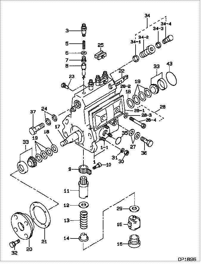
| 000. | [01] | 09010-06361 | BODY ASSY, INJECTI | |
| 001. | [01] | 19011-00963 | HOUSING KIT, INJEC | |
| 001-001. | [03] | 94904-30010 | BOLT, STUD | 85265-00057 |
| 003. | [04] | 09013-10010 | HOLDER, DELIVERY V | 09013-10010 |
| 005. | [04] | 09013-60040 | SPRING, DELIVERY V | 09013-60040 |
| 006. | [04] | 09013-70010 | GASKET, DELIVERY V | 85265-00019 |
| 007. | [04] | 09014-00061 | VALVE SUB-ASSY, IN | |
| 008. | [04] | 09015-03720 | ELEMENT SUB-ASSY, | |
| 009. | [04] | 09015-60010 | PINION, PLUNGER CO | 85265-00074 |
| 010. | [04] | 09015-70010 | SCREW, PLUNGER CON | 85265-00027 |
| 011. | [04] | 09016-10330 | SLEEVE, PLUNGER CO | |
| 012. | [04] | 09016-30010 | SEAT, SPRING, UPR | 09016-30010 |
| 012. | [04] | 09016-30191 | SEAT, SPRING, UPR | |
| 013. | [04] | 09016-40090 | SPRING, PUMP PLUNG | 09016-40090 |
| 014. | [04] | 09016-50160 | SEAT, SPRING, LWR | 09016-50160 |
| 015. | [04] | 09017-00070 | TAPPET SUB-ASSY,IN | 09017-00070 |
| 016. | [04] | 09018-90090 | PLUG, INJECTION PU | 09018-90090 |
| 017. | [01] | 09019-10082 | CAMSHAFT, INJECTIO | 09019-10081 |
| 018. | [02] | 09019-30020 | RING, CAMSHAFT ADJ | 09019-30020 |
| 019. | [6C] | 09019-40010 | PLATE, CAMSHAFT SH | 09019-40010 |
| 019. | [6C] | 09019-40290 | PLATE, CAMSHAFT SH | |
| 019. | [6C] | 09019-40150 | PLATE, CAMSHAFT SH | |
| 019. | [6C] | 09019-40140 | PLATE, CAMSHAFT SH | |
| 019. | [6C] | 09019-40110 | PLATE, CAMSHAFT SH | 09019-40110 |
| 019. | [6C] | 09019-40060 | PLATE, CAMSHAFT SH | 09019-40060 |
| 019. | [6C] | 09019-40050 | PLATE, CAMSHAFT SH | 09019-40050 |
| 019. | [6C] | 09019-40040 | PLATE, CAMSHAFT SH | 09019-40040 |
| 019. | [6C] | 09019-40030 | PLATE, CAMSHAFT SH | 09019-40030 |
| 019. | [6C] | 09019-40020 | PLATE, CAMSHAFT SH | 09019-40020 |
| 020. | [01] | 09020-10300 | COVER, BEARING | 09020-10300 |
| 021. | [01] | 09020-60160 | GASKET, BEARING CO | |
| 021. | [01] | 09020-60010 | GASKET, BEARING CO | 09020-60010 |
| 022. | [01] | 09021-20020 | RACK, CONTROL | |
| 023. | [01] | 09021-50060 | SCREW, RACK GUIDE | 09021-50060 |
| 024. | [02] | 09022-20070 | WASHER, FUEL PIPE | 85265-00079 |
| 025. | [02] | 09023-00031 | PLATE SET, VALVE H | 85265-00052 |
| 027. | [02] | 09025-10010 | WASHER, INJECTION | 85265-00077 |
| 028. | [01] | 09027-01090 | COVER SUB-ASSY, IN | |
| 028. | [01] | 09027-01460 | COVER SUB-ASSY, IN | |
| 028-001. | [01] | 09027-50182 | PROCESSING DRAWING | |
| 028-002. | [01] | 09027-20210 | GASKET, INJECTION | |
| 028-003. | [02] | 09024-30030 | PACKING, AIR BLEED | 85265-00016 |
| 028-004. | [02] | 09027-60030 | SCREW | |
| 029. | [4C] | 09031-10100 | PLATE, TAPPET ADJU | 09031-10100 |
| 029. | [4C] | 09031-10110 | PLATE, TAPPET ADJU | 09031-10110 |
| 029. | [4C] | 09031-10120 | PLATE, TAPPET ADJU | 09031-10120 |
| 029. | [4C] | 09031-10130 | PLATE, TAPPET ADJU | 09031-10130 |
| 029. | [4C] | 09031-10140 | PLATE, TAPPET ADJU | 09031-10140 |
| 029. | [4C] | 09031-10150 | PLATE, TAPPET ADJU | 09031-10150 |
| 029. | [4C] | 09031-10290 | PLATE, TAPPET ADJU | |
| 029. | [4C] | 09031-10090 | PLATE, TAPPET ADJU | 09031-10090 |
| 029. | [4C] | 09031-10080 | PLATE, TAPPET ADJU | 09031-10080 |
| 029. | [4C] | 09031-10010 | PLATE, TAPPET ADJU | 09031-10010 |
| 029. | [4C] | 09031-10020 | PLATE, TAPPET ADJU | 09031-10020 |
| 029. | [4C] | 09031-10030 | PLATE, TAPPET ADJU | 09031-10030 |
| 029. | [4C] | 09031-10040 | PLATE, TAPPET ADJU | 09031-10040 |
| 029. | [4C] | 09031-10050 | PLATE, TAPPET ADJU | 09031-10050 |
| 029. | [4C] | 09031-10060 | PLATE, TAPPET ADJU | 09031-10060 |
| 029. | [4C] | 09031-10070 | PLATE, TAPPET ADJU | 09031-10070 |
| 030. | [03] | 90160-06051 | NUT, HEXAGON | 85265-00085 |
| 031. | [03] | 90258-06001 | WASHER, SPRING | 90258-06001 |
| 032. | [04] | 94904-71360 | BOLT, W/WASHER | 94904-71360 |
| 033. | [02] | 94910-10120 | BEARING, ROLLER | 94910-10121 |
| 034. | [01] | 09024-00010 | BLEEDER SUB-ASSY, | 09024-00010 |
| 034-001. | [01] | 09024-10010 | WASHER, AIR BLEEDE | MM500486 |
| 034-002. | [01] | 09024-20010 | NIPPLE, AIR BLEEDE | 85265-00013 |
| 034-003. | [01] | 09024-30030 | PACKING, AIR BLEED | 85265-00016 |
| 034-004. | [01] | 09024-40010 | SCREW, AIR BLEEDER | 09024-40010 |
| 035. | [01] | 94914-00380 | O-RING | 85265-00084 |
| 036. | [01] | 94918-00060 | SCREW, HOLLOW | 85265-00076 |
| 037. | [01] | 94918-00310 | SCREW, HOLLOW | 85265-00078 |
| 043. | [01] | 94914-00060 | O-RING | 85265-00061 |
Include in #3:
09010-06361
as BODY ASSY, INJECTI
Cross reference number
| Part num | Firm num | Firm | Name |
| 09010-06361 | BODY ASSY, INJECTI |
Information:
Engine Runs Smooth Recommended Procedure1. Engine Used at an Altitude Higher Than 2500 ft. (762 m) At altitudes higher than 2500 ft. (762 m) the rack setting must be changed on 1145, 1150, and 1160 Engines to keep the smoke at a correct level. See the RACK SETTING INFORMATION for the correct rack setting.2. Engine Used in a Lug Condition "Lugging" (when the truck is used in a gear too high for engine rpm to go up as accelerator pedal is pushed farther down, or when the truck is used in a gear where engine rpm goes down with accelerator pedal at maximum travel) the engine causes a reduction in the intake of air with full fuel delivery to the cylinders. Because there is not enough air to burn all the fuel, the fuel that is not used comes out the exhaust as black smoke. To prevent lugging the engine, use a gear where engine can have "acceleration" (increase in speed) under load.3. Dirty Air Cleaner If the air cleaner has a restriction indicator, see if the red piston is in view. If there is no restriction indicator, restriction can be checked with a water manometer or a vacuum gauge (which measures in inches of water). Make the connection to the engine side of the air cleaner or to the engine inlet manifold. Check with the engine running at full load rpm. Maximum restriction is 25 in. (635 mm) of water. If a gauge is not available, visually check the air cleaner element for dirt. If the element is dirty, clean the element or install a new element.4. Air Inlet Piping Damage or Restriction Make a visual inspection of the air inlet system and check for damage to piping, rags in the inlet piping, or damage to the rain cap or the cap pushed too far on the inlet pipe. If no damage is seen, check inlet restriction with a clean air cleaner element.5. Exhaust System Restriction Make a visual inspection of the exhaust system. Check for damage to piping or for a bad muffler. If no damage is found, check the system by removing the exhaust pipes from the exhaust manifolds. With the exhaust pipes removed, start and run the engine to see if the problem is corrected.6. Fuel Injection Timing Not Correct Check and make necessary adjustments as per Testing and Adjusting section of the Service Manual.7. Rack Setting Too High Check and make necessary adjustments as per Testing and Adjusting section of the Service Manual. See the RACK SETTING INFORMATION for the correct rack setting.8. Low Quality Fuel Test the engine with fuel according to recommendations by the Caterpillar Tractor Co.9. Valve Adjustment Not Correct or Valve Leakage Check and make necessary adjustments as per Testing and Adjusting section of the Service Manual. Intake valve adjustment is .015 in. (0,38 mm) and exhaust valve adjustment is .025 in. (0,64 mm). Valve leakage normally causes the engine to "misfire" (ignition not regular) and run rough.