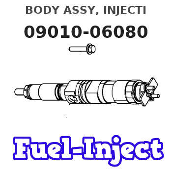
Information body assy, injecti
Rating:
KIT List:
| Body assy, injecti | 1904400320 |
| Body assy, injecti | 1904400320 |
| Body assy, injecti | 1904400320 |
| Body assy, injecti | 1904400320 |
Scheme ###:
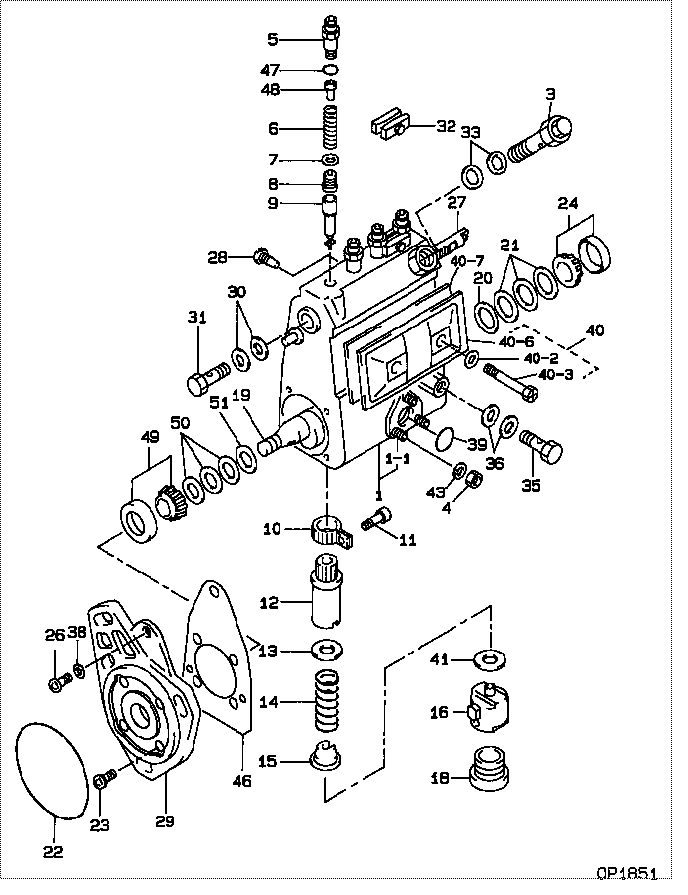
| 000. | [01] | 09010-06080 | BODY ASSY, INJECTI | 22120-58340 |
| 001. | [01] | 19011-03360 | HOUSING KIT, INJEC | 22190-58230 |
| 001-001. | [03] | 94904-30010 | BOLT, STUD | 90099-04071 |
| 003. | [01] | 09031-00130 | VALVE ASSY, OVERFL | 22160-78030 |
| 004. | [03] | 90160-06051 | NUT, HEXAGON | 90092-10101 |
| 005. | [04] | 09013-10320 | HOLDER, DELIVERY V | 22131-78030 |
| 006. | [04] | 09013-60120 | SPRING, DELIVERY V | 22148-78030 |
| 007. | [04] | 09013-70100 | GASKET, DELIVERY V | 22149-78030 |
| 008. | [04] | 09014-01610 | VALVE SUB-ASSY, IN | 22104-58340 |
| 009. | [04] | 09015-03330 | ELEMENT SUB-ASSY, | 22105-58230 |
| 010. | [04] | 09015-60010 | PINION, PLUNGER CO | 22155-76010 |
| 011. | [04] | 09015-70010 | SCREW, PLUNGER CON | 22156-76010 |
| 012. | [02] | 09016-10160 | SLEEVE, PLUNGER CO | 22142-77020 |
| 012. | [02] | 09016-10330 | SLEEVE, PLUNGER CO | 22142-58230 |
| 013. | [04] | 09016-30010 | SEAT, SPRING, UPR | 22143-77020 |
| 013. | [04] | 09016-30191 | SEAT, SPRING, UPR | |
| 014. | [04] | 09016-40090 | SPRING, PUMP PLUNG | 22144-46010 |
| 015. | [04] | 09016-50160 | SEAT, SPRING, LWR | |
| 016. | [04] | 09017-00070 | TAPPET SUB-ASSY,IN | 22106-46010 |
| 018. | [04] | 09018-90090 | PLUG, INJECTION PU | |
| 018. | [04] | 09018-90060 | PLUG, INJECTION PU | 22157-48023 |
| 019. | [01] | 09019-10970 | CAMSHAFT, INJECTIO | 22146-58230 |
| 019. | [01] | 09019-10880 | CAMSHAFT, INJECTIO | |
| 020. | [01] | 09019-30020 | RING, CAMSHAFT ADJ | 22147-77020 |
| 021. | [3C] | 09019-40050 | PLATE, CAMSHAFT SH | 22165-76010 |
| 021. | [3C] | 09019-40040 | PLATE, CAMSHAFT SH | 22164-76010 |
| 021. | [3C] | 09019-40030 | PLATE, CAMSHAFT SH | 22163-76010 |
| 021. | [3C] | 09019-40020 | PLATE, CAMSHAFT SH | 22162-76010 |
| 021. | [3C] | 09019-40010 | PLATE, CAMSHAFT SH | 22161-76010 |
| 021. | [3C] | 09019-40060 | PLATE, CAMSHAFT SH | 22166-76010 |
| 022. | [01] | 94914-03690 | O-RING | 90099-14079 |
| 023. | [04] | 94900-72471 | SCREW, W/WASHER | 90099-00928 |
| 024. | [01] | 94910-10120 | BEARING, ROLLER | 90033-66011 |
| 026. | [01] | 94900-62961 | SCREW | 90099-00894 |
| 027. | [01] | 09021-20020 | RACK, CONTROL | 22114-36010 |
| 028. | [01] | 09021-50060 | SCREW, RACK GUIDE | 22115-78140 |
| 028. | [01] | 09021-50011 | SCREW, RACK GUIDE | 22115-77020 |
| 029. | [01] | 09020-40240 | FLANGE, INJECTION | 22181-58230 |
| 030. | [02] | 09022-20070 | WASHER, FUEL PIPE | 94712-77121 |
| 031. | [01] | 94918-00310 | SCREW, HOLLOW | 90099-18010 |
| 032. | [02] | 09023-00050 | PLATE SET, VALVE H | 22102-58230 |
| 032. | [02] | 09023-00031 | PLATE SET, VALVE H | 22102-77021 |
| 033. | [02] | 09024-10010 | WASHER, AIR BLEEDE | 22119-77020 |
| 035. | [01] | 94918-00680 | SCREW, HOLLOW | 90401-10006 |
| 036. | [02] | 94901-81570 | WASHER, COPPER PLA | 90099-01451 |
| 038. | [01] | 94901-81020 | WASHER, COPPER PLA | 90201-08106 |
| 039. | [01] | 94914-00380 | O-RING | 90099-14015 |
| 040. | [01] | 09027-00961 | COVER SUB-ASSY, IN | |
| 040-002. | [02] | 09024-30030 | PACKING, AIR BLEED | |
| 040-003. | [02] | 09027-60030 | SCREW | |
| 040-003. | [02] | 09027-60020 | SCREW | |
| 040-006. | [01] | 09027-50182 | PROCESSING DRAWING | |
| 040-007. | [01] | 09027-20210 | GASKET, INJECTION | |
| 041. | [4C] | 09031-10100 | PLATE, TAPPET ADJU | 22182-46010 |
| 041. | [4C] | 09031-10110 | PLATE, TAPPET ADJU | 22183-46010 |
| 041. | [4C] | 09031-10120 | PLATE, TAPPET ADJU | 22184-46010 |
| 041. | [4C] | 09031-10130 | PLATE, TAPPET ADJU | 22185-46010 |
| 041. | [4C] | 09031-10140 | PLATE, TAPPET ADJU | 22186-46010 |
| 041. | [4C] | 09031-10150 | PLATE, TAPPET ADJU | 22186-48010 |
| 041. | [4C] | 09031-10090 | PLATE, TAPPET ADJU | 22189-48036 |
| 041. | [4C] | 09031-10080 | PLATE, TAPPET ADJU | 22189-48035 |
| 041. | [4C] | 09031-10070 | PLATE, TAPPET ADJU | 22189-48034 |
| 041. | [4C] | 09031-10010 | PLATE, TAPPET ADJU | 22187-46010 |
| 041. | [4C] | 09031-10020 | PLATE, TAPPET ADJU | 22188-46010 |
| 041. | [4C] | 09031-10030 | PLATE, TAPPET ADJU | 22189-46010 |
| 041. | [4C] | 09031-10040 | PLATE, TAPPET ADJU | 22189-48031 |
| 041. | [4C] | 09031-10050 | PLATE, TAPPET ADJU | 22189-48032 |
| 041. | [4C] | 09031-10060 | PLATE, TAPPET ADJU | 22189-48033 |
| 043. | [03] | 90258-06001 | WASHER, SPRING | 94511-00600 |
| 046. | [01] | 09020-60080 | GASKET, BEARING CO | 22195-58230 |
| 046. | [01] | 09020-60180 | GASKET, BEARING CO | |
| 047. | [04] | 94914-02570 | O-RING | |
| 048. | [04] | 09013-30010 | STOPPER, DELIVERY | |
| 049. | [01] | 94910-10071 | BEARING, ROLLER | 90099-10151 |
| 050. | [3C] | 09019-40360 | PLATE, CAMSHAFT SH | 22166-78144 |
| 050. | [3C] | 09019-40350 | PLATE, CAMSHAFT SH | 22166-78143 |
| 050. | [3C] | 09019-40340 | PLATE, CAMSHAFT SH | 22166-78142 |
| 050. | [3C] | 09019-40100 | PLATE, CAMSHAFT SH | |
| 050. | [3C] | 09019-40090 | PLATE, CAMSHAFT SH | |
| 050. | [3C] | 09019-40080 | PLATE, CAMSHAFT SH | |
| 050. | [3C] | 09019-40070 | PLATE, CAMSHAFT SH | |
| 051. | [01] | 09019-30050 | RING, CAMSHAFT ADJ |
Include in #3:
Cross reference number
| Part num | Firm num | Firm | Name |
| 09010-06080 | 22120-5834 | BODY ASSY, INJECTI | |
| 22120-58340 | TOYOTA | BODY ASSY, INJECTI |
Information:
1. Remove bolts (1) and the locks that hold oil pump (2) in position.2. Remove oil pump (2).Install Oil Pump
1. Put oil pump (1) in position on the engine. Install the bolts and locks that hold it to the engine.end by: a) install oil panDisassemble Oil Pump
start by: a) remove oil pump
TYPICAL EXAMPLE1. Remove pressure relief valve exhaust tube (6).2. Remove suction tube and screen assembly (3).3. Remove the pressure relief valve housing (5). Remove plunger (1), spring (4) and spacer (2) from valve housing (5). 4. Remove the cotter pin from the gear retaining nut. Loosen the nut that holds the gear until it is even with the end of the shaft. Install tooling (A) and make a separation of gear (7) from the shaft.5. Remove tooling (A), retaining nut, gear and woodruff key. 6. Remove the bolts that hold the pump housing. Remove pump housing (8), gear (10) and shaft assembly (9). 7. Use tooling (B) to remove the bearing from the pump housing and gear.Assemble Engine Oil Pump
1. Use tooling (A) to install the bearings in the pump housings and gear.2. Put clean SAE 30 engine oil on the shafts and gear.3. Install the gear and shaft assembly in the pump housing, and connect the pump housings. After bolts that hold the pump housing have been tightened the pump gears must turn freely. 4. Install the woodruff key, drive gear and retaining nut (1). Tighten the nut that holds the gear to 100 lb.ft. (135.6 N m) plus enough to make alignment of cotter pin hole. Install cotter pin.
TYPICAL EXAMPLE5. Put lubrication on and install the spacer, spring and plunger in the pressure relief valve housing. Install the housing assembly (3).6. Install the pressure relief valve exhaust tube (4).7. Install the suction tube and screen assembly (2).end by: a) install oil pump