Information body assy, injecti
Rating:
KIT List:
| Body assy, injecti | 1904400340 |
| Body assy, injecti | 1904400340 |
| Body assy, injecti | 1904400340 |
| Body assy, injecti | 1904400340 |
| Body assy, injecti | 1904400340 |
Scheme ###:
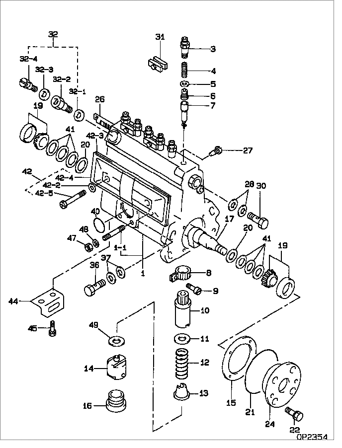
| 000. | [01] | 09010-05910 | BODY ASSY, INJECTI | 22120-68052 |
| 001. | [01] | 19011-02500 | HOUSING KIT, INJEC | 22190-68010 |
| 001-001. | [03] | 94904-30010 | BOLT, STUD | 90099-07071 |
| 003. | [06] | 09013-10010 | HOLDER, DELIVERY V | 22131-77020 |
| 004. | [06] | 09013-60591 | SPRING, DELIVERY V | 22148-68010 |
| 005. | [06] | 09013-70010 | GASKET, DELIVERY V | 22149-76010 |
| 006. | [06] | 09014-00560 | VALVE SUB-ASSY, IN | DES11-00079 |
| 007. | [06] | 09015-02900 | ELEMENT SUB-ASSY, | |
| 008. | [06] | 09015-60010 | PINION, PLUNGER CO | 22155-76010 |
| 009. | [06] | 09015-70010 | SCREW, PLUNGER CON | 22156-76010 |
| 010. | [06] | 09016-10160 | SLEEVE, PLUNGER CO | 22142-67010 |
| 010. | [06] | 09016-10330 | SLEEVE, PLUNGER CO | 22142-58230 |
| 011. | [06] | 09016-30010 | SEAT, SPRING, UPR | 22143-77020 |
| 011. | [06] | 09016-30191 | SEAT, SPRING, UPR | |
| 012. | [06] | 09016-40090 | SPRING, PUMP PLUNG | 22144-46010 |
| 013. | [06] | 09016-50020 | SEAT, SPRING, LWR | 22145-46010 |
| 014. | [06] | 09017-00070 | TAPPET SUB-ASSY,IN | 22106-46010 |
| 015. | [01] | 09020-60170 | GASKET, BEARING CO | |
| 015. | [01] | 09020-60060 | GASKET, BEARING CO | 22195-68010 |
| 016. | [06] | 09018-90060 | PLUG, INJECTION PU | 22157-48023 |
| 016. | [06] | 09018-90090 | PLUG, INJECTION PU | 22157-48024 |
| 017. | [01] | 09019-10710 | CAMSHAFT, INJECTIO | 22146-68010 |
| 019. | [02] | 94910-10120 | BEARING, ROLLER | 90033-66011 |
| 020. | [02] | 09019-30020 | RING, CAMSHAFT ADJ | 22147-77020 |
| 021. | [01] | 94914-02210 | O-RING | 90301-64004 |
| 022. | [04] | 91418-06201 | BOLT, W/WASHER | |
| 024. | [01] | 09020-10390 | COVER, BEARING | 22111-68010 |
| 026. | [01] | 09021-20412 | RACK, CONTROL | 22114-77130 |
| 027. | [01] | 09021-50010 | SCREW, RACK GUIDE | 22115-77020 |
| 027. | [01] | 09021-50060 | SCREW, RACK GUIDE | 22115-78140 |
| 028. | [02] | 09022-20070 | WASHER, FUEL PIPE | 94712-77121 |
| 030. | [01] | 94918-00310 | SCREW, HOLLOW | 90099-18010 |
| 031. | [03] | 09023-00031 | PLATE SET, VALVE H | 22102-67010 |
| 032. | [01] | 09024-00010 | BLEEDER SUB-ASSY, | 22107-67010 |
| 032-001. | [01] | 09024-10010 | WASHER, AIR BLEEDE | 22119-77020 |
| 032-002. | [01] | 09024-20010 | NIPPLE, AIR BLEEDE | 22118-77020 |
| 032-003. | [01] | 09024-30030 | PACKING, AIR BLEED | 22121-77020 |
| 032-004. | [01] | 09024-40010 | SCREW, AIR BLEEDER | 22117-77020 |
| 036. | [01] | 94918-00680 | SCREW, HOLLOW | 90401-10006 |
| 037. | [02] | 94901-81570 | WASHER, COPPER PLA | 90099-01451 |
| 040. | [01] | 94914-00380 | O-RING | 90099-14015 |
| 041. | [6C] | 09019-40060 | PLATE, CAMSHAFT SH | 22166-76010 |
| 041. | [6C] | 09019-40050 | PLATE, CAMSHAFT SH | 22165-76010 |
| 041. | [6C] | 09019-40040 | PLATE, CAMSHAFT SH | 22164-76010 |
| 041. | [6C] | 09019-40030 | PLATE, CAMSHAFT SH | 22163-76010 |
| 041. | [6C] | 09019-40020 | PLATE, CAMSHAFT SH | 22162-76010 |
| 041. | [6C] | 09019-40010 | PLATE, CAMSHAFT SH | 22161-76010 |
| 042. | [01] | 09027-00941 | COVER SUB-ASSY, IN | 22101-77130 |
| 042-002. | [01] | 09024-30030 | PACKING, AIR BLEED | 22121-77020 |
| 042-003. | [01] | 09027-20220 | GASKET, INJECTION | |
| 042-004. | [01] | 09027-50083 | PROCESSING DRAWING | |
| 042-005. | [02] | 09027-60020 | SCREW | 22154-76051 |
| 042-005. | [02] | 09027-60030 | SCREW | |
| 044. | [01] | 09045-30050 | STAY, INJECTION PU | 22177-68010 |
| 045. | [02] | 91410-08141 | BOLT, W/WASHER | 91611-40814 |
| 047. | [03] | 90160-06051 | NUT, HEXAGON | 90092-10101 |
| 048. | [03] | 90258-06001 | WASHER, SPRING | 94511-00600 |
| 049. | [6C] | 09031-10140 | PLATE, TAPPET ADJU | 22186-46010 |
| 049. | [6C] | 09031-10130 | PLATE, TAPPET ADJU | 22185-46010 |
| 049. | [6C] | 09031-10120 | PLATE, TAPPET ADJU | 22184-46010 |
| 049. | [6C] | 09031-10110 | PLATE, TAPPET ADJU | 22183-46010 |
| 049. | [6C] | 09031-10100 | PLATE, TAPPET ADJU | 22182-46010 |
| 049. | [6C] | 09031-10090 | PLATE, TAPPET ADJU | 22189-48036 |
| 049. | [6C] | 09031-10080 | PLATE, TAPPET ADJU | 22189-48035 |
| 049. | [6C] | 09031-10070 | PLATE, TAPPET ADJU | 22189-48034 |
| 049. | [6C] | 09031-10060 | PLATE, TAPPET ADJU | 22189-48033 |
| 049. | [6C] | 09031-10050 | PLATE, TAPPET ADJU | 22189-48032 |
| 049. | [6C] | 09031-10040 | PLATE, TAPPET ADJU | 22189-48031 |
| 049. | [6C] | 09031-10030 | PLATE, TAPPET ADJU | 22189-46010 |
| 049. | [6C] | 09031-10020 | PLATE, TAPPET ADJU | 22188-46010 |
| 049. | [6C] | 09031-10010 | PLATE, TAPPET ADJU | 22187-46010 |
| 049. | [6C] | 09031-10150 | PLATE, TAPPET ADJU | 22186-48010 |
Include in #3:
Cross reference number
| Part num | Firm num | Firm | Name |
| 09010-05910 | 22120-6805 | BODY ASSY, INJECTI | |
| 22120-68052 | TOYOTA | BODY ASSY, INJECTI |
Information:
Fuel System
FUEL SYSTEM
1. Damper. 2. Injection pump housing. 3. Fuel supply line. 4. Fuel return line. 5. Air vent valve. 6. Fuel tank. 7. Priming pump. 8. Transfer pump. 9. Bypass valve. 10. Main fuel filter.This engine has a pressure type fuel system. There is one injection pump and injection valve for each cylinder. The injection pumps are in pump housing (2) on the right side of the engine. The injection valves are in the precombustion chambers in the cylinder head under the valve cover.The transfer pump (8) pulls fuel from fuel tank (6) through the primary filter and main filter (10). It sends the fuel through fuel supply line (3) to the manifold of the injection pump housing. The fuel in the manifold goes to the injection pumps. The injection pumps are in time with the engine and send fuel to the injection valves under high pressure.Bypass valve (9) gives control to the fuel pressure. The extra fuel from the valve goes back to the tank through return line (4).Open air vent valve (5) and use priming pump (7) to remove air from the fuel filter, fuel lines, and components.Damper (1) prevents sharp pressure increases in the system.Fuel Injection Pump Operation
Injection pump plungers (5) and lifters (8) are lifted by cams on camshaft (9) and always make a full stroke. The force of springs (6) hold the lifters (8) against the cams of the camshaft.Fuel from fuel manifold (1) goes through inlet port (2) in the barrel and then into the chamber above plunger (5). During injection, the camshaft cam moves plunger (5) up in the barrel. This movement will close inlet port (2) and push the fuel out through the fuel lines to the injection valves.The amount of fuel sent to the injection valves is controlled by turning plunger (5) in the barrel. When the governor moves fuel rack (7), the fuel rack moves gear (4) that is fastened to the bottom of plunger (5).
FUEL INJECTION PUMP HOUSING
1. Fuel manifold. 2. Inlet port. 3. Check valve. 4. Gear segment. 5. Pump plunger. 6. Spring. 7. Fuel rack. 8. Lifter. 9. Camshaft.Hydra-Mechanical Governor
The accelerator pedal, or governor control, is connected to the control lever on the engine governor. The governor controls the amount of fuel needed to keep the desired engine rpm.The governor has governor weights (15), driven by the engine, governor spring (5), valve (14) and piston (13). The valve and piston are connected to fuel rack (10). The pressure oil for the governor comes from the engine oil pump. Pressure oil goes through passage (11) and around sleeve (12). The accelerator pedal, or governor control, controls only the compression of governor spring (5). Compression of the spring always pushes to give more fuel to the engine. The centrifugal force (rotation) of governor weights (15) is always pulling to get a reduction of fuel to the engine. When these two forces are in balance, the engine runs at the desired rpm (governed rpm).The governor valve is