Information body assy, injecti
Rating:
KIT List:
| Body assy, injecti | 1904400340 |
| Body assy, injecti | 1904400340 |
Scheme ###:
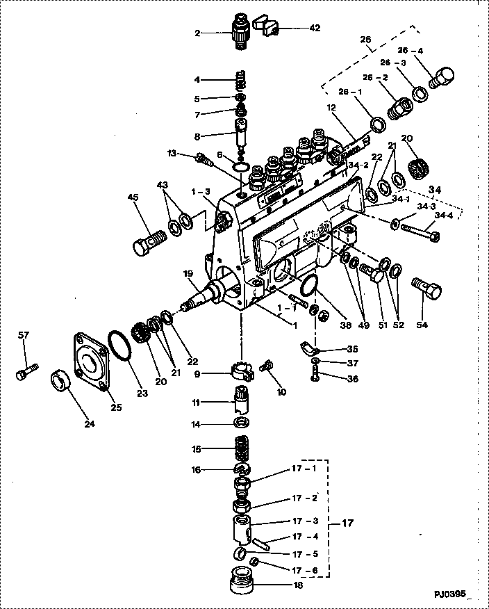
| 000. | [01] | 09010-05600 | BODY ASSY, INJECTI | |
| 001. | [01] | 19011-02970 | HOUSING KIT, INJEC | |
| 001-001. | [03] | 94904-30010 | BOLT, STUD | 22857-1060A |
| 001-003. | [01] | 09022-10010 | UNION, INJECTION P | 22841-1520 |
| 002. | [06] | 09013-10530 | HOLDER, DELIVERY V | 22116-1080A |
| 004. | [06] | 09013-60020 | SPRING, DELIVERY V | |
| 005. | [06] | 09013-70110 | GASKET, DELIVERY V | 22847-1090A |
| 006. | [06] | 90801-10180 | O-RING | 22817-1130A |
| 007. | [06] | 09014-00260 | VALVE SUB-ASSY, IN | |
| 008. | [06] | 09015-03270 | ELEMENT SUB-ASSY, | |
| 009. | [06] | 09015-60010 | PINION, PLUNGER CO | 22128-1020A |
| 010. | [06] | 09015-70010 | SCREW, PLUNGER CON | 22865-1280A |
| 011. | [06] | 09016-10160 | SLEEVE, PLUNGER CO | 22118-1090A |
| 011. | [06] | 09016-10330 | SLEEVE, PLUNGER CO | 22118-1310A |
| 012. | [01] | 09021-20010 | RACK, CONTROL | 22113-1320A |
| 013. | [01] | 09021-50060 | SCREW, RACK GUIDE | |
| 014. | [06] | 09016-30191 | SEAT, SPRING, UPR | |
| 014. | [06] | 09016-30010 | SEAT, SPRING, UPR | 2214D-77020 |
| 015. | [06] | 09016-40010 | SPRING, PUMP PLUNG | 6 056 1200 80 |
| 016. | [06] | 09016-50010 | SEAT, SPRING, LWR | 22122-1060 |
| 017. | [06] | 09017-00130 | TAPPET SUB-ASSY,IN | 22105-1260 |
| 017-001. | [06] | 09017-30010 | BOLT, INJECTION PU | 0901H-30010 |
| 017-002. | [06] | 09017-40010 | NUT, INJECTION PUM | 6 053 1252 40 |
| 017-003. | [06] | 09016-90130 | BODY, INJECTION PU | 22145-1010 |
| 017-004. | [06] | 09017-60010 | PIN, INJECTION PUM | 22105-1130 |
| 017-005. | [06] | 09018-10030 | ROLLER, INJECTION | 22146-1010A |
| 017-006. | [06] | 09017-80030 | BUSHING, INJECTION | 22837-1140A |
| 018. | [06] | 09018-90090 | PLUG, INJECTION PU | 22845-1420A |
| 019. | [01] | 09019-10220 | CAMSHAFT, INJECTIO | 22160-1020 |
| 020. | [02] | 94910-10120 | BEARING, ROLLER | 22837-1230A |
| 021. | [ C] | 09019-40150 | PLATE, CAMSHAFT SH | 22129-1200A |
| 021. | [ C] | 09019-40140 | PLATE, CAMSHAFT SH | 22129-1190A |
| 021. | [ C] | 09019-40060 | PLATE, CAMSHAFT SH | 22885-4950A |
| 021. | [ C] | 09019-40050 | PLATE, CAMSHAFT SH | 22885-4940A |
| 021. | [ C] | 09019-40040 | PLATE, CAMSHAFT SH | 22885-4930A |
| 021. | [ C] | 09019-40030 | PLATE, CAMSHAFT SH | 22885-4920A |
| 021. | [ C] | 09019-40020 | PLATE, CAMSHAFT SH | 22885-4910A |
| 021. | [ C] | 09019-40010 | PLATE, CAMSHAFT SH | 22885-4900A |
| 022. | [02] | 09019-30020 | RING, CAMSHAFT ADJ | 22124-1160A |
| 023. | [01] | 09020-60030 | GASKET, BEARING CO | |
| 024. | [01] | 94915-01750 | SEAL, OIL | 22823-1220 |
| 025. | [01] | 09020-10090 | COVER, BEARING | 22111-1180 |
| 026. | [01] | 09024-00010 | BLEEDER SUB-ASSY, | 22106-1060 |
| 026-001. | [01] | 09024-10010 | WASHER, AIR BLEEDE | 22847-2150A |
| 026-002. | [01] | 09024-20010 | NIPPLE, AIR BLEEDE | 22873-1250 |
| 026-003. | [01] | 09024-30030 | PACKING, AIR BLEED | 22843-1540A |
| 026-004. | [01] | 09024-40010 | SCREW, AIR BLEEDER | 2211H-77020 |
| 034. | [01] | 09027-00691 | COVER SUB-ASSY, IN | 22170-1080 |
| 034-001. | [01] | 09027-50083 | PROCESSING DRAWING | 22127-1220A |
| 034-002. | [01] | 09027-20220 | GASKET, INJECTION | 22847-2180A |
| 034-003. | [02] | 09024-30030 | PACKING, AIR BLEED | 22843-1540A |
| 034-004. | [02] | 09027-60030 | SCREW | 22815-1550A |
| 035. | [01] | 09036-10040 | BEARING, CENTER | 22837-1090A |
| 036. | [02] | 91050-05351 | SCREW, CROSSRECESS | 22815-2400A |
| 036. | [02] | 94900-66550 | SCREW | |
| 037. | [02] | 94901-81030 | WASHER, COPPER PLA | 22867-1020A |
| 038. | [01] | 94914-00380 | O-RING | 22817-1540A |
| 042. | [03] | 09023-00050 | PLATE SET, VALVE H | 22131-1150A |
| 043. | [02] | 94901-02490 | WASHER | 22877-1100A |
| 045. | [01] | 94918-00310 | SCREW, HOLLOW | 22811-2630A |
| 049. | [02] | 94901-02470 | WASHER | 22847-1900A |
| 051. | [01] | 94918-00060 | SCREW, HOLLOW | 27364-1290A |
| 052. | [02] | 94901-02500 | WASHER | 22847-1920A |
| 054. | [01] | 94918-00420 | SCREW, HOLLOW | 22835-1180A |
| 057. | [04] | 94904-71360 | BOLT, W/WASHER | 22815-2500A |
Include in #3:
09010-05600
as BODY ASSY, INJECTI
Cross reference number
| Part num | Firm num | Firm | Name |
| 09010-05600 | BODY ASSY, INJECTI |
Information:
1. Preparation of vehicle for fuel consumption test (consult dynamometer manufacturer's operating instructions for specific details on correct operation). Always perform the Primary Engine Test procedure before vehicle is installed on chassis dynamometer.a. Place vehicle on the chassis dynamometer. Tie the vehicle in a way that will not add any load to the drive wheels. Do not pull wheels down into dynamometer drive rolls. Check the radiator coolant level, crankcase oil level, tire pressure, tire condition, remove rocks from the tire tread and connect exhaust system.
Recapped tires should be run on a chassis dynamometer only at the customer's own risk.
b. The maximum acceptable fuel rate must be calculated for the customer's engine by use of the formula that follows: Find the rated brake specific fuel consumption (lb-bhp/hr) from the RACK SETTING INFORMATION and add .010 in. manufacturing tolerance. Multiply this value by the advertised engine horsepower (plus 3% manf. tol.) and divide by the density of the fuel (lbs/gal).c. Calculate the allowable limits that the customer can expect from his engine and present these figures to him. Caterpillar engines are rated with the conditions that follow: Measure and record these variables. Advertised engine bhp (less 3% manufacturing tolerance) can then be corrected to test conditions by use of procedure and correction tables found in Special Instruction GEG01024.2. Operate vehicle at 60% of rated speed with moderate load until oil and coolant temperatures reach their normal range for operation.
If there is a heavy vibration, drive shaft whip, tire bounce, etc., do not continue with dynamometer test until cause of the problem is corrected. Engines that have had new internal parts installed should be operated on a run-in schedule before operation at full load.
Put transmission in direct gear and the differential in the highest speed ratio. Operate vehicle at maximum engine speed and increase chassis dynamometer load until a speed of 50 rpm less than rated speed is reached (continuity light should be on). Maintain this speed for one minute and record the engine speed, wheel horsepower and fuel rate.3. If the fuel rate and the wheel horsepower are both acceptable, then the engine is not the cause of the complaint, or the complaint is not valid. Refer to section PROBLEM WITH VEHICLE OR VEHICLE OPERATION.4. If the wheel horsepower is low, regardless of how the fuel rate measures, refer to the LOW POWER TROUBLESHOOTING CHART. The low power problem must be corrected first.5. If fuel rate and wheel horsepower are both too high, check the balance point of the engine (speed at which the load stop pin just touches the torque spring or stop bar). At this point the continuity light should flicker (go off and on dimly). If the balance point is high, the high idle will have to be decreased to lower the balance point to the correct rpm (point at which the continuity light just comes on). If the balance point is correct, see Procedure No. 8.6. If the fuel rate is high and the wheel