Information body assy, injecti
Rating:
KIT List:
| Body assy, injecti | No Application |
| Body assy, injecti | No Application |
Scheme ###:
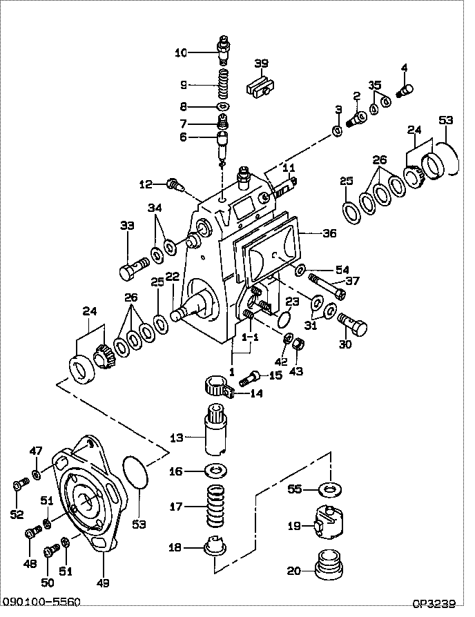
| 000. | [01] | 09010-05560 | BODY ASSY, INJECTI | |
| 001. | [01] | 19011-02281 | HOUSING KIT, INJEC | |
| 001-001. | [03] | 94904-30010 | BOLT, STUD | 85265-00057 |
| 002. | [01] | 09024-20080 | NIPPLE, AIR BLEEDE | |
| 003. | [01] | 09024-10010 | WASHER, AIR BLEEDE | 85265-00014 |
| 004. | [01] | 09031-00050 | VALVE ASSY, OVERFL | 09031-00050 |
| 004. | [01] | 09031-00130 | VALVE ASSY, OVERFL | |
| 006. | [02] | 09015-00050 | ELEMENT SUB-ASSY, | 09015-00050 |
| 007. | [02] | 09014-00061 | VALVE SUB-ASSY, IN | 85265-00072 |
| 008. | [02] | 09013-70010 | GASKET, DELIVERY V | 85265-00019 |
| 009. | [02] | 09013-60040 | SPRING, DELIVERY V | 09013-60040 |
| 010. | [02] | 09013-10540 | HOLDER, DELIVERY V | |
| 011. | [01] | 09021-20070 | RACK, CONTROL | 09021-20070 |
| 012. | [01] | 09021-50011 | SCREW, RACK GUIDE | 85265-00024 |
| 012. | [01] | 09021-50060 | SCREW, RACK GUIDE | 09021-50060 |
| 013. | [02] | 09016-10160 | SLEEVE, PLUNGER CO | 85265-00073 |
| 013. | [02] | 09016-10330 | SLEEVE, PLUNGER CO | |
| 014. | [02] | 09015-60010 | PINION, PLUNGER CO | 85265-00074 |
| 015. | [02] | 09015-70010 | SCREW, PLUNGER CON | 85265-00027 |
| 016. | [02] | 09016-30010 | SEAT, SPRING, UPR | 09016-30010 |
| 016. | [02] | 09016-30191 | SEAT, SPRING, UPR | |
| 017. | [02] | 09016-40090 | SPRING, PUMP PLUNG | 09016-40090 |
| 018. | [02] | 09016-50160 | SEAT, SPRING, LWR | |
| 019. | [02] | 09017-00070 | TAPPET SUB-ASSY,IN | 09017-00070 |
| 020. | [02] | 09018-90060 | PLUG, INJECTION PU | 85265-00075 |
| 022. | [01] | 09019-10231 | CAMSHAFT, INJECTIO | 09019-10230 |
| 023. | [01] | 94914-00380 | O-RING | 85265-00084 |
| 024. | [02] | 94910-10120 | BEARING, ROLLER | 94910-10121 |
| 025. | [02] | 09019-30020 | RING, CAMSHAFT ADJ | 09019-30020 |
| 026. | [ C] | 09019-40010 | PLATE, CAMSHAFT SH | 09019-40010 |
| 026. | [ C] | 09019-40020 | PLATE, CAMSHAFT SH | 09019-40020 |
| 026. | [ C] | 09019-40030 | PLATE, CAMSHAFT SH | 09019-40030 |
| 026. | [ C] | 09019-40040 | PLATE, CAMSHAFT SH | 09019-40040 |
| 026. | [ C] | 09019-40050 | PLATE, CAMSHAFT SH | 09019-40050 |
| 026. | [ C] | 09019-40060 | PLATE, CAMSHAFT SH | 09019-40060 |
| 026. | [ C] | 09019-40400 | PLATE, CAMSHAFT SH | |
| 030. | [01] | 94918-00690 | SCREW, HOLLOW | |
| 031. | [02] | 09025-10010 | WASHER, INJECTION | 85265-00077 |
| 033. | [01] | 94918-00310 | SCREW, HOLLOW | 85265-00078 |
| 034. | [02] | 09022-20070 | WASHER, FUEL PIPE | 85265-00079 |
| 035. | [02] | 09022-20060 | WASHER, FUEL PIPE | 09022-20060 |
| 036. | [01] | 09027-00750 | COVER SUB-ASSY, IN | 09027-00750 |
| 036-001. | [01] | 09027-10270 | PLATE, INJECTION P | |
| 036-002. | [01] | 09027-20040 | GASKET, INJECTION | 09027-20040 |
| 037. | [01] | 09027-60030 | SCREW | |
| 039. | [01] | 09023-00031 | PLATE SET, VALVE H | 85265-00052 |
| 042. | [03] | 90258-06001 | WASHER, SPRING | 90258-06001 |
| 043. | [03] | 90160-06051 | NUT, HEXAGON | 85265-00085 |
| 047. | [01] | 94901-81020 | WASHER, COPPER PLA | 94901-81020 |
| 048. | [01] | 94900-72660 | SCREW, W/WASHER | |
| 048. | [01] | 94900-72661 | SCREW, W/WASHER | |
| 049. | [01] | 09020-40140 | FLANGE, INJECTION | 09020-40140 |
| 050. | [03] | 94900-72471 | SCREW, W/WASHER | |
| 051. | [04] | 90258-08001 | WASHER, SPRING | CSA915D100 |
| 052. | [01] | 94900-62961 | SCREW | 94900-62960 |
| 053. | [02] | 94914-00060 | O-RING | 85265-00061 |
| 054. | [01] | 09024-30030 | PACKING, AIR BLEED | 85265-00016 |
| 055. | [ C] | 09031-10140 | PLATE, TAPPET ADJU | 09031-10140 |
| 055. | [ C] | 09031-10130 | PLATE, TAPPET ADJU | 09031-10130 |
| 055. | [ C] | 09031-10120 | PLATE, TAPPET ADJU | 09031-10120 |
| 055. | [ C] | 09031-10110 | PLATE, TAPPET ADJU | 09031-10110 |
| 055. | [ C] | 09031-10100 | PLATE, TAPPET ADJU | 09031-10100 |
| 055. | [ C] | 09031-10090 | PLATE, TAPPET ADJU | 09031-10090 |
| 055. | [ C] | 09031-10080 | PLATE, TAPPET ADJU | 09031-10080 |
| 055. | [ C] | 09031-10070 | PLATE, TAPPET ADJU | 09031-10070 |
| 055. | [ C] | 09031-10060 | PLATE, TAPPET ADJU | 09031-10060 |
| 055. | [ C] | 09031-10050 | PLATE, TAPPET ADJU | 09031-10050 |
| 055. | [ C] | 09031-10040 | PLATE, TAPPET ADJU | 09031-10040 |
| 055. | [ C] | 09031-10030 | PLATE, TAPPET ADJU | 09031-10030 |
| 055. | [ C] | 09031-10020 | PLATE, TAPPET ADJU | 09031-10020 |
| 055. | [ C] | 09031-10010 | PLATE, TAPPET ADJU | 09031-10010 |
| 055. | [ C] | 09031-10150 | PLATE, TAPPET ADJU | 09031-10150 |
Include in #3:
09010-05560
as BODY ASSY, INJECTI
Cross reference number
| Part num | Firm num | Firm | Name |
| 09010-05560 | BODY ASSY, INJECTI |
Information:
1. Governor linkage. 2. Exhaust manifold. 3. Aftercooler. 4. Turbocharger. 5. Alternator. 6. Fan. 7. Fuel injection pump. 8. Fuel filter. 9. Fuel priming pump. 10. Cover for drive gear for fuel injection pump. 11. Housing for water temperature regulator. 12. Air compressor. 13. Inlet manifold. 14. Bracket covering timing pointer for flywheel timing marks. 15. Water pump. 16. Damper. 17. Front engine support. 18. Position for power steering pump. 19. Oil filter. 20. Oil cooler. 21. Information plates.The 3306 Truck Engine is a 4.75 in. (120.6 mm) bore, 6.00 in. (152.40 mm) stroke turbocharged engine. It is available with a watercooled aftercooler. This engine has six cylinders with a displacement of 638 cu. in. (10.5 liters). The firing order is 1, 5, 3, 6, 2, 4.The 3306 Truck Engine uses a Sleeve Metering Fuel System with a shutoff solenoid.The starting system is direct electric and uses a 12 volt starting motor. It can also be equipped with an optional 24 volt system.Fuel System
Introduction
The Sleeve Metering Fuel System is a pressure type fuel system. The name for the system is from the method used to control the amount of fuel in the fuel injection charge. This system has an injection pump and an injection valve for each cylinder. The injection pumps are in the fuel injection pump housing on the right side of the engine. The injection valves are in the precombustion chambers in the cylinder head.Fuel System Timing
An automatic timing advance unit connects the drive sleeve on the end of the camshaft to the timing gears in the front of the engine. The unit changes the timing of the fuel system according to the engine speed to give better combustion of the fuel at all levels of engine operation. The unit in the turbocharged engine changes injection timing from 12° BTC, at 1200 rpm, to 18° BTC, at 2200 rpm. The unit in the turbocharged and aftercooled engine changes injection timing from 8° 30' BTC, at 1200 rpm, to 14° 30' BTC, at 2200 rpm.Water Separator
Some engines have a water separator. The water separator is installed between the fuel tank and the rest of the fuel system. For efficiency in the action of the water separator the fuel flow must come directly from the fuel tank and through the water separator. This is because the action of going through a pump or valves before the water separator lowers the efficiency of the water separator.The water separator can remove 95% of the water in a fuel flow of up to 33 gph (125 liter/hr) if the concentration of the water in the fuel is 10% or less. It is important to check the water level in the water separator frequently. The maximum amount of water which the water separator can hold is 0.8 pt. (0.4 liter). At this point the water fills the glass to 3/4 full. Do not let the water separator have this much water before draining the water. After the water level is at 3/4