Information body assy, injecti

Rating:
KIT List:
| Body assy, injecti | No Application |
| Body assy, injecti | No Application |
Scheme ###:
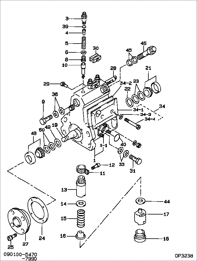
| 000. | [01] | 09010-05470 | BODY ASSY, INJECTI | |
| 001. | [01] | 19011-03270 | HOUSING KIT, INJEC | |
| 001-001. | [01] | 94904-30010 | BOLT, STUD | 85265-00057 |
| 003. | [03] | 09013-10650 | HOLDER, DELIVERY V | |
| 004. | [03] | 09013-30260 | STOPPER, DELIVERY | |
| 005. | [03] | 09013-60710 | SPRING, DELIVERY V | |
| 006. | [03] | 09013-70100 | GASKET, DELIVERY V | 09013-70100 |
| 008. | [03] | 09014-01420 | VALVE SUB-ASSY, IN | |
| 009. | [01] | 94918-00310 | SCREW, HOLLOW | 85265-00078 |
| 010. | [03] | 09015-03230 | ELEMENT SUB-ASSY, | |
| 011. | [03] | 09015-60010 | PINION, PLUNGER CO | 85265-00074 |
| 012. | [03] | 09015-70010 | SCREW, PLUNGER CON | 85265-00027 |
| 013. | [03] | 09016-10160 | SLEEVE, PLUNGER CO | 85265-00073 |
| 013. | [03] | 09016-10330 | SLEEVE, PLUNGER CO | |
| 014. | [03] | 09016-30010 | SEAT, SPRING, UPR | 09016-30010 |
| 014. | [01] | 09016-30191 | SEAT, SPRING, UPR | |
| 015. | [03] | 09016-40090 | SPRING, PUMP PLUNG | 09016-40090 |
| 016. | [03] | 09016-50160 | SEAT, SPRING, LWR | 09016-50160 |
| 017. | [03] | 09017-00070 | TAPPET SUB-ASSY,IN | 09017-00070 |
| 018. | [03] | 09018-90060 | PLUG, INJECTION PU | 85265-00075 |
| 018. | [03] | 09018-90090 | PLUG, INJECTION PU | 09018-90090 |
| 019. | [01] | 09019-10900 | CAMSHAFT, INJECTIO | 09019-10900 |
| 021. | [01] | 94910-10120 | BEARING, ROLLER | 94910-10121 |
| 022. | [01] | 09019-30020 | RING, CAMSHAFT ADJ | 09019-30020 |
| 023. | [ C] | 09019-40400 | PLATE, CAMSHAFT SH | |
| 023. | [ C] | 09019-40060 | PLATE, CAMSHAFT SH | 09019-40060 |
| 023. | [ C] | 09019-40050 | PLATE, CAMSHAFT SH | 09019-40050 |
| 023. | [ C] | 09019-40040 | PLATE, CAMSHAFT SH | 09019-40040 |
| 023. | [ C] | 09019-40030 | PLATE, CAMSHAFT SH | 09019-40030 |
| 023. | [ C] | 09019-40020 | PLATE, CAMSHAFT SH | 09019-40020 |
| 023. | [ C] | 09019-40070 | PLATE, CAMSHAFT SH | 09019-40070 |
| 024. | [01] | 09020-60040 | GASKET, BEARING CO | |
| 024. | [01] | 09020-60150 | GASKET, BEARING CO | |
| 025. | [04] | 91418-06201 | BOLT, W/WASHER | 91418-06201 |
| 027. | [01] | 09020-10351 | COVER, BEARING | 09020-10351 |
| 028. | [01] | 09021-20050 | RACK, CONTROL | EZ40057028 |
| 029. | [01] | 09021-50060 | SCREW, RACK GUIDE | 09021-50060 |
| 029. | [01] | 09021-50011 | SCREW, RACK GUIDE | 09021-50011 |
| 030. | [02] | 09023-00060 | PLATE SET, VALVE H | |
| 031. | [01] | 94918-00690 | SCREW, HOLLOW | |
| 033. | [02] | 09025-10010 | WASHER, INJECTION | 85265-00077 |
| 034. | [01] | 09027-01150 | COVER SUB-ASSY, IN | |
| 034. | [01] | 09027-01250 | COVER SUB-ASSY, IN | |
| 034-001. | [01] | 09027-50133 | PROCESSING DRAWING | |
| 034-002. | [01] | 09027-20200 | GASKET, INJECTION | |
| 034-003. | [02] | 09024-30030 | PACKING, AIR BLEED | 85265-00016 |
| 034-004. | [02] | 09027-60030 | SCREW | |
| 036. | [02] | 09022-20070 | WASHER, FUEL PIPE | 85265-00079 |
| 039. | [03] | 94914-02570 | O-RING | 94914-02570 |
| 040. | [01] | 94914-00380 | O-RING | 85265-00084 |
| 044. | [ C] | 09031-10150 | PLATE, TAPPET ADJU | 09031-10150 |
| 044. | [ C] | 09031-10140 | PLATE, TAPPET ADJU | 09031-10140 |
| 044. | [ C] | 09031-10130 | PLATE, TAPPET ADJU | 09031-10130 |
| 044. | [ C] | 09031-10120 | PLATE, TAPPET ADJU | 09031-10120 |
| 044. | [ C] | 09031-10110 | PLATE, TAPPET ADJU | 09031-10110 |
| 044. | [ C] | 09031-10100 | PLATE, TAPPET ADJU | 09031-10100 |
| 044. | [ C] | 09031-10090 | PLATE, TAPPET ADJU | 09031-10090 |
| 044. | [ C] | 09031-10080 | PLATE, TAPPET ADJU | 09031-10080 |
| 044. | [ C] | 09031-10070 | PLATE, TAPPET ADJU | 09031-10070 |
| 044. | [ C] | 09031-10060 | PLATE, TAPPET ADJU | 09031-10060 |
| 044. | [ C] | 09031-10050 | PLATE, TAPPET ADJU | 09031-10050 |
| 044. | [ C] | 09031-10040 | PLATE, TAPPET ADJU | 09031-10040 |
| 044. | [ C] | 09031-10030 | PLATE, TAPPET ADJU | 09031-10030 |
| 044. | [ C] | 09031-10020 | PLATE, TAPPET ADJU | 09031-10020 |
| 044. | [ C] | 09031-10010 | PLATE, TAPPET ADJU | 09031-10010 |
| 045. | [02] | 09022-20060 | WASHER, FUEL PIPE | 09022-20060 |
| 046. | [01] | 09031-00130 | VALVE ASSY, OVERFL | |
| 046. | [01] | 09031-00050 | VALVE ASSY, OVERFL | 09031-00050 |
| 048. | [01] | 94910-10071 | BEARING, ROLLER | |
| 049. | [01] | 09019-30050 | RING, CAMSHAFT ADJ | |
| 050. | [ C] | 09019-40070 | PLATE, CAMSHAFT SH | 09019-40070 |
| 050. | [ C] | 09019-40080 | PLATE, CAMSHAFT SH | 09019-40080 |
| 050. | [ C] | 09019-40090 | PLATE, CAMSHAFT SH | 09019-40090 |
| 050. | [ C] | 09019-40100 | PLATE, CAMSHAFT SH | 09019-40100 |
| 050. | [ C] | 09019-40410 | PLATE, CAMSHAFT SH |
Include in #3:
09010-05470
as BODY ASSY, INJECTI
Cross reference number
| Part num | Firm num | Firm | Name |
| 09010-05470 | BODY ASSY, INJECTI |
Information:
start by:a) remove fuel injection pump housing and governorb) remove governor
Be careful not to cause damage to the inlet and outlet ports on the bottom of the pump housing. The pump housing must be put on wood blocks before it is disassembled.
1. Remove bolts (3) from rear cover (2). Remove cover (2) and gasket. 2. Remove the shaft and gear from cover (2). Remove bushing (4) from the cover. 3. Remove bolts (10) that hold retainer (11) and gear (9) to the pump camshaft. Remove the retainer and gear.4. Remove the bolts and cover (1) from the pump housing.5. Remove idler gear (5). Remove pinion gear (8) from the pump housing with a soft hammer. Remove drive gear (6).6. Remove cover (7). 7. Remove bolts (14) from levers (17). Pull shaft (12) out of the pump housing. Remove levers (17), bushing (13) and spring (15).8. Remove bypass valve (16). Remove O-ring seal, pin, piston and spring from the valve body. 9. Remove bushing (18) from each of the injection pumps with tool (A). Remove washers (19).10. Put identification on each injection pump as to its location in the pump housing. Hold the fuel racks in the center (zero) position and carefully remove each injection pump with tool (B). 11. Remove the bolt that holds bracket (20) to the fuel injection pump housing. Remove bracket (20) and link (21). 12. Put identification on the left rack (25) and right rack (24). Remove fuel racks (24) and (25).13. Remove spacer (23) and lifter (22) from the pump housing. Put identification on each of the spacers and lifters as to their location in the pump housing. 14. Remove camshaft (26) from the pump housing.15. Remove the upper and lower bearings that hold the pinion gear in the pump housing. 16. Remove the dowel and idler gear shaft from the pump housing with tool group (C). 17. Remove fuel rack bearings (27) from the fuel pump housing. 18. Remove the lip type seals and bearings (29) from the pump housing with tooling (D).19. Remove the camshaft front and rear bearings (28) with tool group (E).Assemble Fuel Injection Pump Housing
1. Put fixture assembly (1) [part of tooling (A)] on the fuel pump housing with the dowels of the fixture in alignment with the left rack bore. Install the bolt that holds the fixture to the pump housing. 2. Put a new bearing (2) in position between the fixture and the fuel rack bore with the tab of the bearing up. Put driver (3) [part of tooling (A)] in alignment with the bearing until the shoulder of the driver makes contact with the bottom of the fixture.3. Turn the fixture and make alignment of the dowels in the fixture with the right rack bore. Install the bolt that holds the fixture to the pump housing.4. Do Step 2 for the left fuel rack bearing. 5. Install the camshaft front and rear bearings with tool group (B). Install the rear bearing until it is .28