Information body assy, injecti
Rating:
Scheme ###:
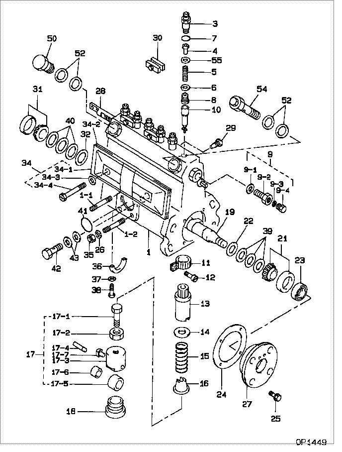
| 000. | [01] | 09010-04960 | BODY ASSY, INJECTI | |
| 001. | [01] | 19011-03050 | HOUSING KIT, INJEC | ME702627 |
| 001-001. | [01] | 94904-30010 | BOLT, STUD | ME702091 |
| 001-002. | [02] | 94904-31630 | BOLT, STUD | ME702092 |
| 003. | [06] | 09013-10420 | HOLDER, DELIVERY V | ME703579 |
| 004. | [06] | 09013-30140 | STOPPER, DELIVERY | ME703580 |
| 005. | [06] | 09013-60490 | SPRING, DELIVERY V | ME728287 |
| 006. | [06] | 09013-70110 | GASKET, DELIVERY V | ME702624 |
| 007. | [06] | 90801-10180 | O-RING | ME702649 |
| 008. | [06] | 09014-01250 | VALVE SUB-ASSY, IN | ME703516 |
| 009. | [01] | 09024-00010 | BLEEDER SUB-ASSY, | ME702083 |
| 009-001. | [01] | 09024-10010 | WASHER, AIR BLEEDE | ME702102 |
| 009-002. | [01] | 09024-20010 | NIPPLE, AIR BLEEDE | ME022094 |
| 009-003. | [01] | 09024-30030 | PACKING, AIR BLEED | ME702057 |
| 009-004. | [01] | 09024-40010 | SCREW, AIR BLEEDER | MM501930 |
| 010. | [06] | 09015-02850 | ELEMENT SUB-ASSY, | ME703518 |
| 011. | [06] | 09015-60010 | PINION, PLUNGER CO | ME702058 |
| 012. | [06] | 09015-70010 | SCREW, PLUNGER CON | ME702059 |
| 013. | [06] | 09016-10330 | SLEEVE, PLUNGER CO | ME702060 |
| 014. | [06] | 09016-30010 | SEAT, SPRING, UPR | ME702061 |
| 014. | [06] | 09016-30191 | SEAT, SPRING, UPR | ME736080 |
| 015. | [06] | 09016-40010 | SPRING, PUMP PLUNG | ME702062 |
| 016. | [06] | 09016-50010 | SEAT, SPRING, LWR | ME702063 |
| 017. | [06] | 09017-00130 | TAPPET SUB-ASSY,IN | ME702064 |
| 017-001. | [06] | 09017-30010 | BOLT, INJECTION PU | ME702066 |
| 017-002. | [06] | 09017-40010 | NUT, INJECTION PUM | ME702067 |
| 017-003. | [06] | 09017-10173 | TAPPET, INJECTION | |
| 017-003. | [06] | 09016-90130 | BODY, INJECTION PU | ME702065 |
| 017-004. | [06] | 09017-60010 | PIN, INJECTION PUM | ME702068 |
| 017-005. | [06] | 09018-10030 | ROLLER, INJECTION | ME702070 |
| 017-006. | [06] | 09017-80030 | BUSHING, INJECTION | ME702069 |
| 017-007. | [06] | 09017-50040 | SLIDER | ME736247 |
| 018. | [06] | 09018-90090 | PLUG, INJECTION PU | ME703276 |
| 019. | [01] | 09019-10620 | CAMSHAFT, INJECTIO | ME702072 |
| 021. | [01] | 94910-10071 | BEARING, ROLLER | ME702562 |
| 022. | [01] | 09019-30050 | RING, CAMSHAFT ADJ | ME702073 |
| 023. | [01] | 94915-01620 | SEAL, OIL | ME702099 |
| 024. | [01] | 09020-60150 | GASKET, BEARING CO | ME728350 |
| 024. | [01] | 09020-60040 | GASKET, BEARING CO | ME702078 |
| 025. | [04] | 91418-06201 | BOLT, W/WASHER | ME702041 |
| 027. | [01] | 09020-10371 | COVER, BEARING | ME702077 |
| 028. | [01] | 09021-20010 | RACK, CONTROL | ME702079 |
| 029. | [01] | 09021-50060 | SCREW, RACK GUIDE | ME728163 |
| 029. | [01] | 09021-50011 | SCREW, RACK GUIDE | ME702080 |
| 030. | [03] | 09023-00050 | PLATE SET, VALVE H | ME702558 |
| 031. | [01] | 94910-10120 | BEARING, ROLLER | ME702096 |
| 032. | [01] | 09019-30020 | RING, CAMSHAFT ADJ | ME702074 |
| 034. | [01] | 09027-00690 | COVER SUB-ASSY, IN | ME702084 |
| 034. | [01] | 09027-00622 | COVER SUB-ASSY, IN | 09027-00621 |
| 034-001. | [01] | 09027-50083 | PROCESSING DRAWING | ME702602 |
| 034-002. | [01] | 09027-20220 | GASKET, INJECTION | ME702085 |
| 034-003. | [02] | 09024-30030 | PACKING, AIR BLEED | ME702057 |
| 034-004. | [02] | 09027-60030 | SCREW | ME703028 |
| 036. | [01] | 09036-10040 | BEARING, CENTER | ME702088 |
| 037. | [02] | 94901-81030 | WASHER, COPPER PLA | ME702094 |
| 038. | [02] | 91050-05351 | SCREW, CROSSRECESS | ME702597 |
| 038. | [02] | 94900-66550 | SCREW | ME736044 |
| 039. | [3C] | 09019-40410 | PLATE, CAMSHAFT SH | ME728353 |
| 039. | [3C] | 09019-40170 | PLATE, CAMSHAFT SH | ME703271 |
| 039. | [3C] | 09019-40160 | PLATE, CAMSHAFT SH | ME703270 |
| 039. | [3C] | 09019-40100 | PLATE, CAMSHAFT SH | MM500694 |
| 039. | [3C] | 09019-40090 | PLATE, CAMSHAFT SH | MM500693 |
| 039. | [3C] | 09019-40080 | PLATE, CAMSHAFT SH | MM500692 |
| 039. | [3C] | 09019-40070 | PLATE, CAMSHAFT SH | ME702076 |
| 040. | [3C] | 09019-40400 | PLATE, CAMSHAFT SH | ME728352 |
| 040. | [3C] | 09019-40290 | PLATE, CAMSHAFT SH | ME703274 |
| 040. | [3C] | 09019-40150 | PLATE, CAMSHAFT SH | ME703273 |
| 040. | [3C] | 09019-40140 | PLATE, CAMSHAFT SH | ME703272 |
| 040. | [3C] | 09019-40110 | PLATE, CAMSHAFT SH | ME703583 |
| 040. | [3C] | 09019-40060 | PLATE, CAMSHAFT SH | ME022103 |
| 040. | [3C] | 09019-40050 | PLATE, CAMSHAFT SH | ME022102 |
| 040. | [3C] | 09019-40040 | PLATE, CAMSHAFT SH | ME022101 |
| 040. | [3C] | 09019-40030 | PLATE, CAMSHAFT SH | ME022100 |
| 040. | [3C] | 09019-40020 | PLATE, CAMSHAFT SH | ME022099 |
| 040. | [3C] | 09019-40010 | PLATE, CAMSHAFT SH | ME702075 |
| 041. | [01] | 94914-00380 | O-RING | ME702097 |
| 042. | [01] | 09083-80012 | PLUG, DRAIN | ME022504 |
| 043. | [02] | 09025-10010 | WASHER, INJECTION | ME702595 |
| 050. | [01] | 94918-00310 | SCREW, HOLLOW | ME702236 |
| 052. | [04] | 09022-20070 | WASHER, FUEL PIPE | ME702217 |
| 054. | [01] | 09031-00110 | VALVE ASSY, OVERFL | ME702087 |
| 055. | [6C] | 94901-35020 | WASHER, PLATE, SK | ME702628 |
| 055. | [6C] | 94901-35030 | WASHER, PLATE, SK | ME702741 |
| 055. | [6C] | 94901-36730 | WASHER, PLATE, SK | ME703328 |
Include in #3:
09010-04960
as BODY ASSY, INJECTI
Cross reference number
| Part num | Firm num | Firm | Name |
| 09010-04960 | BODY ASSY, INJECTI |
Information:
Introduction
For Specifications with illustrations, make reference to ENGINE SPECIFICATIONS FOR 4.5" BORE, V8 VEHICLE ENGINE (Direct Injection) Form No. REG01270. If the Specifications in Form No. REG01270 are not the same as in the Systems Operation and the Testing and Adjusting, look at the printing date on the back cover of each book. Use the Specifications given in the book with the latest date.Fuel System
The diaphragm-type fuel transfer pump mounts on the fuel injection pump housing and is driven by a lobe on the injection pump camshaft. The pump draws fuel from the tank and delivers it to a spin-on throw-away type filter. The filter is a combination primary-secondary element.Filtered fuel flows through a shutoff solenoid, mounted on the fuel injection pump housing, into a fuel manifold. The solenoid operates electrically and stops fuel flow when the engine electrical system is shut off.Fuel in the manifold flows through the barrel assembly inlet port into the area above the injection pump plunger. During injection, the camshaft forces the plunger upward in the barrel. The end of the plunger closes the inlet port and forces the fuel out through high pressure injection lines to the nozzles.The injection nozzles are located under the valve cover and are held in place by clamps. The nozzle tip projects from the head into the cylinder bore. Atomized fuel is sprayed in a cone-shaped pattern through four .0128 in. (0.325 mm) orifices into the cylinder.During injection, a small amount of fuel leaks past the valve guide in the nozzle body of lubricate its moving parts. Any excess leakage flows from the nozzle to a fuel return manifold under the valve cover of each cylinder head. External lines connect the manifolds and return the fuel to the tank.Governor Operation
The hydraulic governor maintains speed at the rpm selected.When the engine is operating, the balance between the centrifugal force of the revolving weights and the force of the governor spring controls the movement of the valve. The valve directs pressure oil to either side of a rack-positioning piston. Depending upon the position of the valve, the rack is moved to increase or decrease the amount of fuel to the engine to compensate for load variation.
GOVERNOR (Earlier Governor)
1. High idle spring. 2. Weights. 3. Valve. 4. Cylinder. 5. Low idle spring. 6. Piston. 7. Sleeve.
GOVERNOR (Later Governor)
1. Low idle screw. 2. Weights. 3. Valve. 4. Cylinder. 5. High idle spring. 6. Low idle spring. 7. Piston. 8. Sleeve.Pressurized lubrication oil, directed through passages in the fuel injection pump housing, enters a passage in the governor cylinder. The oil encircles a sleeve within the cylinder. This oil is then directed through a passage in the piston, where it contacts the valve.When engine load increases, the revolving weights slow down. The weights move toward each other and allow the governor spring to move the valve forward. As the valve moves, a small passage in the piston opens to pressure oil. Oil flows through this passage and fills the chamber behind the