Information body assy, injecti
Rating:
Scheme ###:
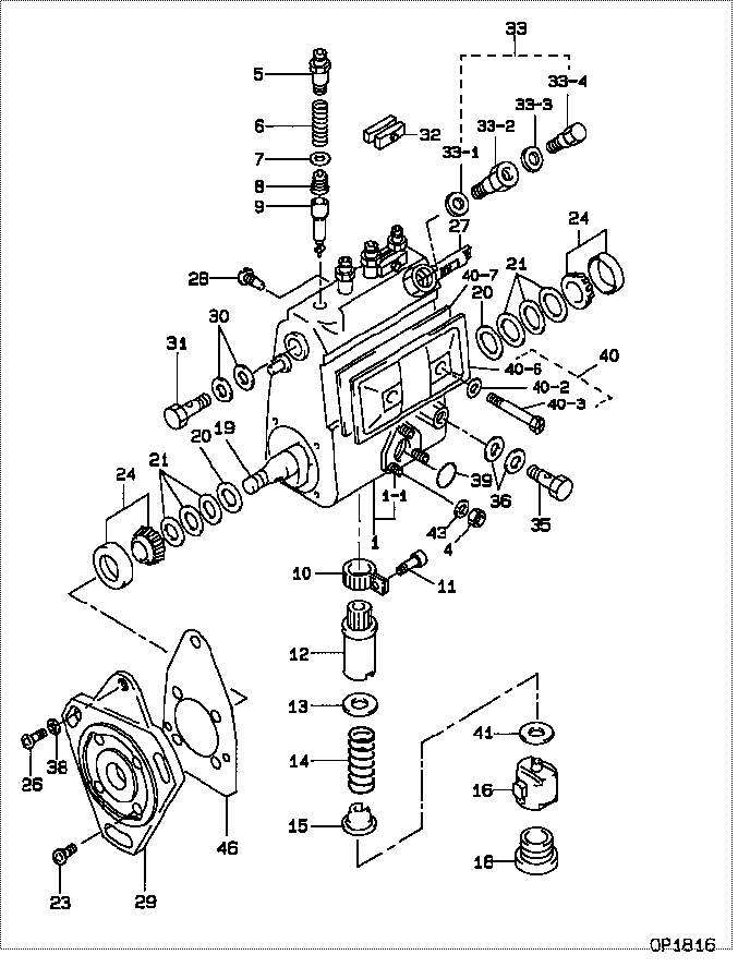
| 000. | [01] | 09010-04920 | BODY ASSY, INJECTI | |
| 001. | [01] | 19011-02182 | HOUSING KIT, INJEC | |
| 001-001. | [03] | 94904-30010 | BOLT, STUD | 90099-04071-000 |
| 004. | [03] | 90160-06051 | NUT, HEXAGON | 94110-40600-000 |
| 005. | [04] | 09013-10010 | HOLDER, DELIVERY V | 22131-77020-000 |
| 006. | [04] | 09013-60050 | SPRING, DELIVERY V | 22148-46010-000 |
| 007. | [04] | 09013-70010 | GASKET, DELIVERY V | 22149-76010-000 |
| 008. | [04] | 09014-00560 | VALVE SUB-ASSY, IN | 22104-68110-000 |
| 009. | [04] | 09015-02411 | ELEMENT SUB-ASSY, | |
| 010. | [04] | 09015-60010 | PINION, PLUNGER CO | 22155-76010-000 |
| 011. | [04] | 09015-70010 | SCREW, PLUNGER CON | 22156-76010-000 |
| 012. | [04] | 09016-10160 | SLEEVE, PLUNGER CO | 22142-77020-000 |
| 012. | [04] | 09016-10330 | SLEEVE, PLUNGER CO | 22142-58230-000 |
| 013. | [04] | 09016-30010 | SEAT, SPRING, UPR | 22143-77020-000 |
| 013. | [04] | 09016-30191 | SEAT, SPRING, UPR | 22143-78150-000 |
| 014. | [04] | 09016-40090 | SPRING, PUMP PLUNG | 22144-46010-000 |
| 015. | [04] | 09016-50160 | SEAT, SPRING, LWR | 22145-78030-000 |
| 016. | [04] | 09017-00070 | TAPPET SUB-ASSY,IN | 22106-46010-000 |
| 018. | [04] | 09018-90090 | PLUG, INJECTION PU | 22157-87302-000 |
| 019. | [01] | 09019-10082 | CAMSHAFT, INJECTIO | 22146-56010-000 |
| 020. | [02] | 09019-30020 | RING, CAMSHAFT ADJ | 22147-77020-000 |
| 021. | [6C] | 09019-40150 | PLATE, CAMSHAFT SH | 22166-78031-000 |
| 021. | [6C] | 09019-40140 | PLATE, CAMSHAFT SH | 22166-78030-000 |
| 021. | [6C] | 09019-40060 | PLATE, CAMSHAFT SH | 22166-76010-000 |
| 021. | [6C] | 09019-40050 | PLATE, CAMSHAFT SH | 22165-76010-000 |
| 021. | [6C] | 09019-40040 | PLATE, CAMSHAFT SH | 22164-76010-000 |
| 021. | [6C] | 09019-40030 | PLATE, CAMSHAFT SH | 22163-76010-000 |
| 021. | [6C] | 09019-40020 | PLATE, CAMSHAFT SH | 22162-76010-000 |
| 021. | [6C] | 09019-40010 | PLATE, CAMSHAFT SH | 22161-76010-000 |
| 023. | [04] | 94900-72471 | SCREW, W/WASHER | 90099-00928-000 |
| 024. | [02] | 94910-10120 | BEARING, ROLLER | 90091-30203-000 |
| 026. | [01] | 94900-62961 | SCREW | 90099-00894-000 |
| 027. | [01] | 09021-20110 | RACK, CONTROL | 22114-46010-000 |
| 028. | [01] | 09021-50011 | SCREW, RACK GUIDE | 22115-77020-000 |
| 028. | [01] | 09021-50060 | SCREW, RACK GUIDE | 22115-78140-000 |
| 029. | [01] | 09020-40221 | FLANGE, INJECTION | |
| 030. | [02] | 09022-20070 | WASHER, FUEL PIPE | 22125-87301-000 |
| 031. | [01] | 94918-00310 | SCREW, HOLLOW | 90099-18010-000 |
| 032. | [02] | 09023-00031 | PLATE SET, VALVE H | 22102-77021-000 |
| 033. | [01] | 09024-00010 | BLEEDER SUB-ASSY, | 22150-67010-000 |
| 033-001. | [01] | 09024-10010 | WASHER, AIR BLEEDE | 22119-77020-000 |
| 033-002. | [01] | 09024-20010 | NIPPLE, AIR BLEEDE | 22118-77020-000 |
| 033-003. | [01] | 09024-30030 | PACKING, AIR BLEED | 22121-77020-000 |
| 033-004. | [01] | 09024-40010 | SCREW, AIR BLEEDER | 22117-77020-000 |
| 035. | [01] | 94918-00680 | SCREW, HOLLOW | 90401-10006-000 |
| 036. | [02] | 94901-81570 | WASHER, COPPER PLA | 90099-01451-000 |
| 038. | [01] | 94901-81020 | WASHER, COPPER PLA | 90201-08106-000 |
| 039. | [01] | 94914-00380 | O-RING | 90099-14015-000 |
| 040. | [01] | 09027-01090 | COVER SUB-ASSY, IN | 22103-48030-000 |
| 040-002. | [02] | 09024-30030 | PACKING, AIR BLEED | 22121-77020-000 |
| 040-003. | [02] | 09027-60030 | SCREW | |
| 040-006. | [01] | 09027-50182 | PROCESSING DRAWING | 22563-78050-000 |
| 040-007. | [01] | 09027-20210 | GASKET, INJECTION | 22153-78030-000 |
| 041. | [4C] | 09031-10100 | PLATE, TAPPET ADJU | 22182-46010-000 |
| 041. | [4C] | 09031-10110 | PLATE, TAPPET ADJU | 22183-46010-000 |
| 041. | [4C] | 09031-10120 | PLATE, TAPPET ADJU | 22184-46010-000 |
| 041. | [4C] | 09031-10130 | PLATE, TAPPET ADJU | 22185-46010-000 |
| 041. | [4C] | 09031-10140 | PLATE, TAPPET ADJU | 22186-46010-000 |
| 041. | [4C] | 09031-10150 | PLATE, TAPPET ADJU | 22186-48010-000 |
| 041. | [4C] | 09031-10090 | PLATE, TAPPET ADJU | 22189-48036-000 |
| 041. | [4C] | 09031-10080 | PLATE, TAPPET ADJU | 22189-48035-000 |
| 041. | [4C] | 09031-10070 | PLATE, TAPPET ADJU | 22189-48034-000 |
| 041. | [4C] | 09031-10010 | PLATE, TAPPET ADJU | 22187-46010-000 |
| 041. | [4C] | 09031-10020 | PLATE, TAPPET ADJU | 22188-46010-000 |
| 041. | [4C] | 09031-10030 | PLATE, TAPPET ADJU | 22189-46010-000 |
| 041. | [4C] | 09031-10040 | PLATE, TAPPET ADJU | 22189-48031-000 |
| 041. | [4C] | 09031-10050 | PLATE, TAPPET ADJU | 22189-48032-000 |
| 041. | [4C] | 09031-10060 | PLATE, TAPPET ADJU | 22189-48033-000 |
| 043. | [03] | 90258-06001 | WASHER, SPRING | 94511-00600-000 |
| 046. | [01] | 09020-60050 | GASKET, BEARING CO | 22195-48030-000 |
| 046. | [01] | 09020-60190 | GASKET, BEARING CO | 22195-87302-000 |
Include in #3:
09010-04920
as BODY ASSY, INJECTI
Cross reference number
| Part num | Firm num | Firm | Name |
| 09010-04920 | BODY ASSY, INJECTI |
Information:
GENERAL
Specifications
General
Wiring Diagrams
Numeral on each wire is a "nominal size" according to JIS. C-3406 Low-voltage Electrical Wiring for Automobiles.(1) For standard type engines with alternator (with built-in IC regulator) or AC dynamo (2) For L2 engines of "Key-OFF stop" specification (With AC dynamo) (3) For standard engines of "Key-OFF stop" specification (4) For L2, L3 engines with glow timer, key-OFF stop specification (5) Three kinds of wiring diagrams for the engines with the "Key-OFF stop" system are shown above. Machines equipped with those engines may be in need of wiring modification to match with those key-OFF stop system circuits. In such a case, careful attention should be paid to the matters mentioned in the below. CAUTION (6) Combination of operations of components in "Key-OFF stop" (fuel cutoff solenoid) system circuit (7) Key switch connection for automatic glow system operations STARTER
Construction
Starter Component Parts(1) Front bracket assembly(2) Lever assembly(3) Spring set(4) Center bracket assembly(5) Switch assembly(6) Through bolt(7) Armature(8) Rear bearing(9) Pinion(10) Pinionshaft assembly(11) Gear(12) Yoke assembly(13) Brush holder assembly(14) Rear bracketInspection (Assembly)
If any abnormality is assumed by the following tests, adjust the starter or disassemble and repair it.(1) Pinion gap inspection(a) Interpose a battery (12V) between starter terminal "S" and starter body, and the pinion will protrude and stop. CAUTION Never apply battery voltage for over 10 seconds continuously.(b) Lightly push the pinion back and measure the return stroke (called pinion gap).(c) If the pinion gap is not within the standard range (0.5 to 2.0 mm), adjust it by increasing or decreasing the number of packings on the magnetic switch. The gap is decreased as the number of packings increases.
Inspecting Pinion Gap(2) No-load test(a) Connect the ammeter, voltmeter and battery to the starter as illustrated.(b) When the switch is closed, the pinion must protrude and the starter must run smoothly (at 3000 rpm or more). If the current or starter speed is out of specification, disassemble the starter and repair it.
No-load Test CAUTION* Use the thick wires as far as possible for wiring and tighten every terminal securely.* This is a solenoid shift type starter which makes a rotating sound larger than that of a direct-drive type starter.* When detecting starter rotation at the pinion tip, take care of protrusion of the pinion.(3) Magnetic switchPerform the following tests. If any test is not satisfied, replace the magnetic switch assembly.(a) Disconnect wire from terminal "M."(b) Attraction testConnect a battery to the magnetic switch terminals S and M. The pinion must protrude.
Attraction Test CAUTION Do not apply battery current for more than 10 seconds.(c) Holding testWith a battery connected to the magnetic switch terminal "S" and to the starter body, manually pull out the pinion fully. The pinion must remain at that position even