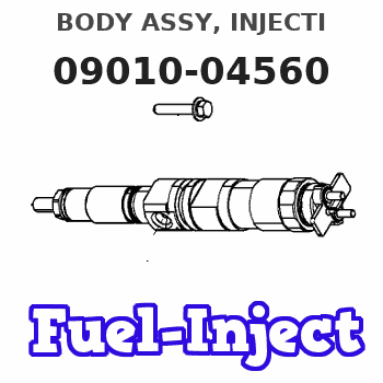
Information body assy, injecti
Rating:
KIT List:
| Body assy, injecti | 1904400360 |
| Body assy, injecti | 1904400360 |
| Body assy, injecti | 1904400360 |
Scheme ###:
| 000. | [01] | 09010-04560 | BODY ASSY, INJECTI | 22130-1480 |
| 000. | [01] | 09010-04560 | BODY ASSY, INJECTI | S2213-01480 |
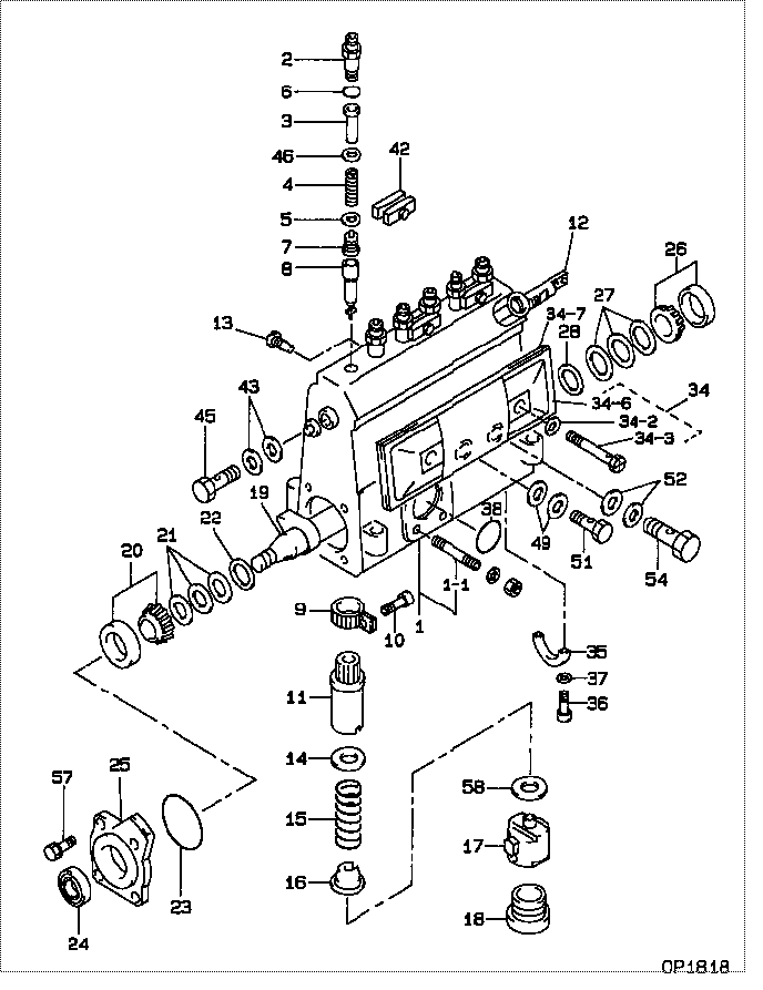
| 001. | [01] | 19011-02401 | HOUSING KIT, INJEC | 22101-1620A |
| 001-001. | [03] | 94904-30010 | BOLT, STUD | 22857-1060A |
| 001-002. | [01] | 09022-10070 | UNION, INJECTION P | 22131-1050A |
| 001-003. | [01] | 09022-10310 | UNION, INJECTION P | 22131-1580A |
| 001-003. | [01] | 09022-10010 | UNION, INJECTION P | 22841-1520 |
| 002. | [06] | 09013-10530 | HOLDER, DELIVERY V | 22116-1080A |
| 003. | [06] | 09013-30010 | STOPPER, DELIVERY | 22117-1040A |
| 004. | [06] | 09013-60450 | SPRING, DELIVERY V | 22125-1020A |
| 005. | [06] | 09013-70110 | GASKET, DELIVERY V | 22847-1090A |
| 006. | [06] | 90801-10180 | O-RING | 22817-1130A |
| 007. | [06] | 09014-00700 | VALVE SUB-ASSY, IN | 22103-1080A |
| 008. | [06] | 09015-02750 | ELEMENT SUB-ASSY, | 22104-2930A |
| 009. | [06] | 09015-60010 | PINION, PLUNGER CO | 22128-1020A |
| 010. | [06] | 09015-70010 | SCREW, PLUNGER CON | 22865-1280A |
| 011. | [06] | 09016-10330 | SLEEVE, PLUNGER CO | 22118-1310A |
| 011. | [06] | 09016-10160 | SLEEVE, PLUNGER CO | 22118-1090A |
| 012. | [01] | 09021-20010 | RACK, CONTROL | 22113-1320A |
| 013. | [01] | 09021-50060 | SCREW, RACK GUIDE | 22811-4850A |
| 014. | [06] | 09016-30120 | SEAT, SPRING, UPR | 22119-1010A |
| 014. | [06] | 09016-30191 | SEAT, SPRING, UPR | 22119-1190A |
| 015. | [06] | 09016-40090 | SPRING, PUMP PLUNG | 22121-1170A |
| 016. | [06] | 09016-50020 | SEAT, SPRING, LWR | 22122-1020A |
| 017. | [06] | 09017-00070 | TAPPET SUB-ASSY,IN | 22105-1020A |
| 018. | [06] | 09018-90090 | PLUG, INJECTION PU | 22845-1420A |
| 019. | [01] | 09019-10550 | CAMSHAFT, INJECTIO | 22123-1050A |
| 020. | [01] | 94910-10071 | BEARING, ROLLER | 22837-1100A |
| 021. | [3C] | 09019-40360 | PLATE, CAMSHAFT SH | 22885-5700A |
| 021. | [3C] | 09019-40350 | PLATE, CAMSHAFT SH | 22885-5690A |
| 021. | [3C] | 09019-40340 | PLATE, CAMSHAFT SH | 22885-5680A |
| 021. | [3C] | 09019-40170 | PLATE, CAMSHAFT SH | 22129-1180A |
| 021. | [3C] | 09019-40160 | PLATE, CAMSHAFT SH | 22129-1170A |
| 021. | [3C] | 09019-40070 | PLATE, CAMSHAFT SH | 22885-1550A |
| 021. | [3C] | 09019-40100 | PLATE, CAMSHAFT SH | 22885-1580A |
| 021. | [3C] | 09019-40090 | PLATE, CAMSHAFT SH | 22885-1570A |
| 021. | [3C] | 09019-40080 | PLATE, CAMSHAFT SH | 22885-1560A |
| 021. | [3C] | 09019-40070 | PLATE, CAMSHAFT SH | 22885-1550A |
| 022. | [01] | 09019-30050 | RING, CAMSHAFT ADJ | 22124-1090A |
| 023. | [01] | 94914-01550 | O-RING | 22817-1110A |
| 024. | [01] | 94915-01620 | SEAL, OIL | 22827-1040A |
| 025. | [01] | 09020-10310 | COVER, BEARING | 22111-1030A |
| 026. | [01] | 94910-10120 | BEARING, ROLLER | 22837-1230A |
| 027. | [3C] | 09019-40150 | PLATE, CAMSHAFT SH | 22129-1200A |
| 027. | [3C] | 09019-40060 | PLATE, CAMSHAFT SH | 22885-4950A |
| 027. | [3C] | 09019-40050 | PLATE, CAMSHAFT SH | 22885-4940A |
| 027. | [3C] | 09019-40040 | PLATE, CAMSHAFT SH | 22885-4930A |
| 027. | [3C] | 09019-40030 | PLATE, CAMSHAFT SH | 22885-4920A |
| 027. | [3C] | 09019-40140 | PLATE, CAMSHAFT SH | 22129-1190A |
| 027. | [3C] | 09019-40020 | PLATE, CAMSHAFT SH | 22885-4910A |
| 027. | [3C] | 09019-40010 | PLATE, CAMSHAFT SH | 22885-4900A |
| 028. | [01] | 09019-30020 | RING, CAMSHAFT ADJ | 22124-1160A |
| 034. | [01] | 09027-00622 | COVER SUB-ASSY, IN | 22170-1690A |
| 034. | [01] | 09027-01041 | COVER SUB-ASSY, IN | 22170-1040A |
| 034-002. | [02] | 09024-30030 | PACKING, AIR BLEED | 22847-1890A |
| 034-003. | [02] | 09027-60030 | SCREW | 22815-1550A |
| 034-006. | [01] | 09027-50083 | PROCESSING DRAWING | 22127-1220A |
| 034-007. | [01] | 09027-20220 | GASKET, INJECTION | 22847-2180A |
| 035. | [01] | 09036-10040 | BEARING, CENTER | 22837-1090A |
| 036. | [02] | 91050-05351 | SCREW, CROSSRECESS | 22815-2400A |
| 036. | [02] | 94900-66550 | SCREW | 22815-3250A |
| 037. | [02] | 94901-81030 | WASHER, COPPER PLA | 22867-1020A |
| 038. | [01] | 94914-00380 | O-RING | 22817-1540A |
| 042. | [01] | 09023-00050 | PLATE SET, VALVE H | 22109-1170A |
| 042. | [01] | 09023-00031 | PLATE SET, VALVE H | 22109-1090A |
| 043. | [02] | 94901-02490 | WASHER | 22877-1100A |
| 045. | [01] | 94918-00310 | SCREW, HOLLOW | 22835-1310A |
| 046. | [ C] | 94901-35050 | WASHER, PLATE, SK | 22885-1460A |
| 046. | [ C] | 94901-35030 | WASHER, PLATE, SK | 22885-1450A |
| 046. | [ C] | 94901-35020 | WASHER, PLATE, SK | 22885-1440A |
| 049. | [02] | 94901-02470 | WASHER | 22847-1900A |
| 051. | [01] | 94918-00060 | SCREW, HOLLOW | 22835-1110A |
| 052. | [02] | 94901-02500 | WASHER | 22847-1920A |
| 054. | [01] | 94918-00420 | SCREW, HOLLOW | 22835-1180A |
| 057. | [04] | 94904-71360 | BOLT, W/WASHER | 22815-2500A |
| 058. | [6C] | 09031-10090 | PLATE, TAPPET ADJU | 22885-1340A |
| 058. | [6C] | 09031-10100 | PLATE, TAPPET ADJU | 22885-1230A |
| 058. | [6C] | 09031-10110 | PLATE, TAPPET ADJU | 22885-1240A |
| 058. | [6C] | 09031-10120 | PLATE, TAPPET ADJU | 22885-1350A |
| 058. | [6C] | 09031-10130 | PLATE, TAPPET ADJU | 22885-1360A |
| 058. | [6C] | 09031-10140 | PLATE, TAPPET ADJU | 22885-1370A |
| 058. | [6C] | 09031-10150 | PLATE, TAPPET ADJU | 22885-1250A |
| 058. | [6C] | 09031-10080 | PLATE, TAPPET ADJU | 22885-1330A |
| 058. | [6C] | 09031-10070 | PLATE, TAPPET ADJU | 22885-1190A |
| 058. | [6C] | 09031-10060 | PLATE, TAPPET ADJU | 22885-1180A |
| 058. | [6C] | 09031-10050 | PLATE, TAPPET ADJU | 22885-1170A |
| 058. | [6C] | 09031-10040 | PLATE, TAPPET ADJU | 22885-1160A |
| 058. | [6C] | 09023-00050 | PLATE SET, VALVE H | 22109-1170A |
| 058. | [6C] | 09031-10030 | PLATE, TAPPET ADJU | 22885-1150A |
| 058. | [6C] | 09031-10020 | PLATE, TAPPET ADJU | 22885-1140A |
| 058. | [6C] | 09031-10010 | PLATE, TAPPET ADJU | 22885-1130A |
| 058. | [6C] | 09031-10290 | PLATE, TAPPET ADJU | 22885-2270A |
Include in #3:
Cross reference number
| Part num | Firm num | Firm | Name |
| 09010-04560 | 22130-1480 | BODY ASSY, INJECTI | |
| 22130-1480A | HINO | BODY ASSY, INJECTI | |
| 22130-1480 | HINO | BODY ASSY, INJECTI | |
| S2213-01480 | HINO | BODY ASSY, INJECTI |
Information:
Introduction
This Special Instruction explains the calibration procedure for the heavy sleeve (commonly called the thick sleeve) metering fuel system. This Special Instruction shows:* The differences between the new 133-8985 Governor And Fuel Injection Pump Group, (HSMFS) and the 109-0324 Governor And Fuel Injection Pump Group, Sleeve Metering Fuel System (SMFS).* Calibration procedure for setting the 124-5932 Lever Assemblies.Recommended Tools
* 4C-9738 Torque Screwdriver set at 1.7 N m (15 lb in).* 4C-9738 Torque Screwdriver set at 4.0 N m (35 lb in).Required Tooling
* 3P-2200 Sleeve Setting Group: The HSMFS Injection Pump Group requires the use of many of the past 3208 Calibration Tools. A few new dedicated tools are required for the HSMFS.
Illustration 1. Parts included, and parts required but not included within the 3P-2200 Sleeve Setting Group. See Chart 1 and Chart 2 for item and part numbers. The 3P-2200 Sleeve Setting Group is used to set, test and adjust SMFS Injection Pump Groups.Reference, Special Instruction; SMHS6988, "Use Of 3P-2200 Calibration Tool Group".Special Instruction, SMHS7013, "Use Of The 5P-4203 Field Service Tool Group Or 5P-6577 Fuel Setting Tool Group". All tools may be stored in a 6V-3073 Plastic Case. The lid contains a 6V-4094 Liner and 6V-4873 Packing in the bottom for protection. The 6V-4873 Packing is topped with a 2P-8289 Tool Holder Block.
Illustration 2. The 5P-4203 Tool Group. See chart 3. for item and part number. 109-0324 Governor And Fuel Injection Pump Group (SMFS).
Illustration 3. View of the 109-0324 Governor And Fuel Injection Pump Group (SMFS). (1) 9N-5820 Lever. (2) 124-5941 Shaft. (3) 9Y-7791 Sleeve.The SMFS Injection Pump Group 9.0 mm (.35 in) 9Y-7791 Sleeve (3) has four 9N-5820 Levers (1) on each 124-5941 Shaft (2). The 9N-5820 Levers are indexed from the front. The 9Y-7791 Sleeve and 9N-5820 Lever indexes with the groove in the 9Y-7791 Sleeve.133-8985 Governor And Fuel Injection Pump Group (HSMFS).
Illustration 4. View of the HSMFS Injection Pump Group.
(1) 124-5932 Lever Assembly. (2) 124-5941 Shaft. (3) 124-5934 Sleeve.
Illustration 5. View of the HSMFS Injection Pump Group.
(1) 124-5932 Lever Assembly. (4) 126-7232 Dowel.The new 124-5934 Sleeve (3) is thicker than the former 9Y-7791 Sleeve (3). The new 124-5934 Sleeve can be operated at higher injection pressures needed for emissions control. As a result of its increased thickness, the 124-5934 Sleeve can not be indexed from the front. It must be indexed between two 124-5934 Sleeves.The new 124-5932 Lever Assembly (1) has a 126-7232 Dowel (4) that is split in half. The split 126-7232 Dowel is positioned between two 133-8984 Fuel Pump Assemblies and indexes two 124-5934 Sleeves (3) at the same time.
Illustration 6. Side view of one bank of the HSMFS Injection Pump Group. (1) 124-5932 Lever Assemblies. (2) 124-5941 Shaft.There are two 124-5932 Lever Assemblies (1) on the 124-5941 Shaft (2) of the HSMFS Injection Pump Group, instead of four 9N-5820 levers (1) on each 124-5941 Shaft (2) on the SMFS Injection Pump Group. Each 124-5932 Lever Assembly is positioned in between two and indexes two 133-8984 Fuel Pump Assemblies and two 124-5934