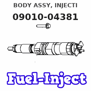
Information body assy, injecti
Rating:
Scheme ###:
| 000. | [01] | 09010-04381 | BODY ASSY, INJECTI | |
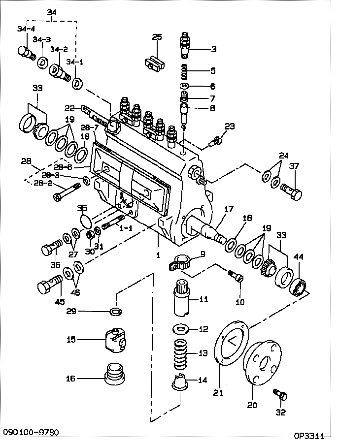
| 001. | [01] | 19011-01992 | HOUSING KIT, INJEC | 22190-31631-71 |
| 001-001. | [03] | 94904-30010 | BOLT, STUD | 90099-04071 |
| 003. | [06] | 09013-10010 | HOLDER, DELIVERY V | 22131-77020 |
| 005. | [06] | 09013-60020 | SPRING, DELIVERY V | 22148-77020 |
| 006. | [06] | 09013-70010 | GASKET, DELIVERY V | 22149-76010 |
| 007. | [06] | 09014-00010 | VALVE SUB-ASSY, IN | 22104-77020 |
| 008. | [06] | 09015-00360 | ELEMENT SUB-ASSY, | 22105-77130 |
| 009. | [06] | 09015-60010 | PINION, PLUNGER CO | 22155-76010 |
| 010. | [06] | 09015-70010 | SCREW, PLUNGER CON | 22156-76010 |
| 011. | [06] | 09016-10330 | SLEEVE, PLUNGER CO | 22142-58230 |
| 012. | [06] | 09016-30191 | SEAT, SPRING, UPR | 22143-78150 |
| 013. | [06] | 09016-40090 | SPRING, PUMP PLUNG | 22144-46010 |
| 014. | [06] | 09016-50160 | SEAT, SPRING, LWR | 22145-78030 |
| 015. | [06] | 09017-00070 | TAPPET SUB-ASSY,IN | 22106-46010 |
| 016. | [06] | 09018-90090 | PLUG, INJECTION PU | 22157-48024 |
| 017. | [01] | 09019-10711 | CAMSHAFT, INJECTIO | 22146-68010 |
| 018. | [02] | 09019-30020 | RING, CAMSHAFT ADJ | 22147-77020 |
| 019. | [6C] | 09019-40400 | PLATE, CAMSHAFT SH | |
| 019. | [6C] | 09019-40290 | PLATE, CAMSHAFT SH | 22166-78141 |
| 019. | [6C] | 09019-40150 | PLATE, CAMSHAFT SH | 22166-78031 |
| 019. | [6C] | 09019-40140 | PLATE, CAMSHAFT SH | 22166-78030 |
| 019. | [6C] | 09019-40110 | PLATE, CAMSHAFT SH | 22166-78140 |
| 019. | [6C] | 09019-40060 | PLATE, CAMSHAFT SH | 22166-76010 |
| 019. | [6C] | 09019-40050 | PLATE, CAMSHAFT SH | 22165-76010 |
| 019. | [6C] | 09019-40040 | PLATE, CAMSHAFT SH | 22164-76010 |
| 019. | [6C] | 09019-40030 | PLATE, CAMSHAFT SH | 22163-76010 |
| 019. | [6C] | 09019-40020 | PLATE, CAMSHAFT SH | 22162-76010 |
| 019. | [6C] | 09019-40010 | PLATE, CAMSHAFT SH | 22161-76010 |
| 020. | [01] | 09020-10240 | COVER, BEARING | 22111-77130 |
| 021. | [01] | 09020-60160 | GASKET, BEARING CO | 22195-77141 |
| 022. | [01] | 09021-20010 | RACK, CONTROL | 22114-67010 |
| 023. | [01] | 09021-50060 | SCREW, RACK GUIDE | 22115-78140 |
| 024. | [02] | 09022-20050 | WASHER, FUEL PIPE | 22122-30890-71 |
| 025. | [03] | 09023-00031 | PLATE SET, VALVE H | 22102-77021 |
| 027. | [02] | 94901-81570 | WASHER, COPPER PLA | 90099-01451 |
| 028. | [01] | 09027-01081 | COVER SUB-ASSY, IN | |
| 028-002. | [02] | 09027-60030 | SCREW | |
| 028-003. | [02] | 94901-03020 | WASHER | 90099-01503 |
| 028-006. | [01] | 09027-50083 | PROCESSING DRAWING | |
| 028-007. | [01] | 09027-20250 | GASKET, INJECTION | |
| 029. | [6C] | 09031-10100 | PLATE, TAPPET ADJU | 22182-46010 |
| 029. | [6C] | 09031-10110 | PLATE, TAPPET ADJU | 22183-46010 |
| 029. | [6C] | 09031-10120 | PLATE, TAPPET ADJU | 22184-46010 |
| 029. | [6C] | 09031-10130 | PLATE, TAPPET ADJU | 22185-46010 |
| 029. | [6C] | 09031-10140 | PLATE, TAPPET ADJU | 22186-46010 |
| 029. | [6C] | 09031-10150 | PLATE, TAPPET ADJU | 22186-48010 |
| 029. | [6C] | 09031-10290 | PLATE, TAPPET ADJU | 22186-78030 |
| 029. | [6C] | 09031-10090 | PLATE, TAPPET ADJU | 22189-48036 |
| 029. | [6C] | 09031-10080 | PLATE, TAPPET ADJU | 22189-48035 |
| 029. | [6C] | 09031-10010 | PLATE, TAPPET ADJU | 22187-46010 |
| 029. | [6C] | 09031-10020 | PLATE, TAPPET ADJU | 22188-46010 |
| 029. | [6C] | 09031-10030 | PLATE, TAPPET ADJU | 22189-46010 |
| 029. | [6C] | 09031-10040 | PLATE, TAPPET ADJU | 22189-48031 |
| 029. | [6C] | 09031-10050 | PLATE, TAPPET ADJU | 22189-48032 |
| 029. | [6C] | 09031-10060 | PLATE, TAPPET ADJU | 22189-48033 |
| 029. | [6C] | 09031-10070 | PLATE, TAPPET ADJU | 22189-48034 |
| 030. | [03] | 90160-06051 | NUT, HEXAGON | 90092-10101 |
| 031. | [03] | 90258-06001 | WASHER, SPRING | 94511-00600 |
| 032. | [04] | 94904-71360 | BOLT, W/WASHER | 90031-19067 |
| 033. | [02] | 94910-10120 | BEARING, ROLLER | 90099-10087 |
| 034. | [01] | 09024-00040 | BLEEDER SUB-ASSY, | |
| 034-001. | [01] | 09024-10010 | WASHER, AIR BLEEDE | 22119-77020 |
| 034-002. | [01] | 09024-20010 | NIPPLE, AIR BLEEDE | 22118-77020 |
| 034-003. | [01] | 09024-80010 | WASHER, DRAIN SCRE | 22378-76010 |
| 034-004. | [01] | 09024-40010 | SCREW, AIR BLEEDER | 22117-77020 |
| 035. | [01] | 94914-01380 | O-RING | 22536-30890-71 |
| 036. | [01] | 94918-00680 | SCREW, HOLLOW | 90401-10006 |
| 037. | [01] | 94918-00310 | SCREW, HOLLOW | 90099-18010 |
| 044. | [01] | 94915-01760 | SEAL, OIL | |
| 045. | [01] | 94918-00420 | SCREW, HOLLOW | 90099-18018 |
| 046. | [02] | 94901-81120 | WASHER, COPPER PLA | 90099-01439 |
Include in #3:
09010-04381
as BODY ASSY, INJECTI
Cross reference number
| Part num | Firm num | Firm | Name |
| 09010-04381 | BODY ASSY, INJECTI |
Information:
2. Remove the four bolts (2) that hold flange to aftercooler cover. Loosen clamp (6) on the turbocharger, and turn housing until inlet pipe is away from camshaft housing.3. Remove the oil drain line for the turbocharger.4. Disconnect the wiring from the glow plugs.5. Remove the inner fuel injection lines (4).6. Disconnect the outer fuel injection lines from the camshaft housing.7. Disconnect the wiring (3) for the glow plugs from the camshaft housing.8. Remove lifting bracket (1) from housing. 9. Remove the two bolts (7), nuts (8), and locks.10. Remove the bolts (5) that hold the camshaft housing in position. 11. Fasten a hoist to the camshaft housing. Remove camshaft housing (9). Weight of housing is 100 lb. (45 kg).Install Camshaft Housing
1. Turn all adjustment screws counterclockwise as far as possible to get maximum valve lash. Turn the camshafts until the "V" timing marks on drive gears (2) and (3) are in alignment as shown. Install the timing pin in timing hole in camshaft housing.2. Check to be sure the No. 1 piston is at the "TOP CENTER COMPRESSION" position, and the timing bolt is installed in flywheel.
The procedure in Steps 1 and 2 must be followed or damage to the engine may result.
3. Fasten a hoist and put camshaft housing in position on engine with gear (3) engaged with gear (4) in cylinder head. Install the bolts (1), nuts, and locks that hold the camshaft housing in position. Install lifting bracket (5).4. Connect the fuel injection lines to outside of camshaft housing. Install inner lines. Tighten the nuts on lines to 30 5 lb.ft. (4.1 0.7 mkg).5. Remove the timing pin from camshaft housing and timing bolt from flywheel.6. Make the valve lash adjustment as follows: Make an adjustment to exhaust valves for cylinders 1-3-5 and inlet valves for cylinders 1-2-4. Turn the crankshaft 360° so No. 6 piston is at "TOP CENTER COMPRESSION" position. Make an adjustment to exhaust valves for cylinders 2-4-6 and inlet valves for cylinders 3-5-6.a) Turn screws clockwise until there is zero clearance between the button on screw and the valve.b) Turn screws counterclockwise four clicks to get .008 in. (0.2 mm) clearance for the inlet valves.c) Turn screws counterclockwise ten clicks to get .020 in. (0.5 mm) clearance for the exhaust valves.7. Connect the wiring for the glow plugs. Install the oil drain line for the turbocharger.8. Turn the housing to put pipe (6) into position, and install the four bolts. Tighten clamp (7).end by: a) install valve coverb) install alternatorDisassemble Camshaft Housing
start by: a) remove camshaft housing 1. Remove the four bolts (3) and lock from each drive gear. Remove the camshaft drive gears (1) and (2). 2. Remove the two bolts (5), lock, and plate (4) that hold camshafts in position. 3. Remove the inlet camshaft (6) and exhaust camshaft (7) from housing.4. Remove lifting bracket (8) from end of camshaft housing. 5. Remove the two bolts (11) that hold the rocker shafts in position.6. Remove the