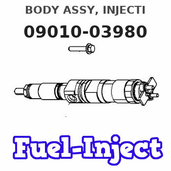
Information body assy, injecti
Rating:
KIT List:
| Body assy, injecti | No Application |
| Body assy, injecti | No Application |
Scheme ###:

| 000. | [01] | 09010-03981 | BODY ASSY, INJECTI | |
| 001. | [01] | 19011-02271 | HOUSING KIT, INJEC | |
| 001-001. | [03] | 94904-30010 | BOLT, STUD | 85265-00057 |
| 002. | [01] | 09024-00010 | BLEEDER SUB-ASSY, | 09024-00010 |
| 002-001. | [01] | 09024-10010 | WASHER, AIR BLEEDE | MM500486 |
| 002-002. | [01] | 09024-20010 | NIPPLE, AIR BLEEDE | 85265-00013 |
| 002-003. | [01] | 09024-30030 | PACKING, AIR BLEED | 85265-00016 |
| 002-004. | [01] | 09024-40010 | SCREW, AIR BLEEDER | 09024-40010 |
| 006. | [02] | 09015-00050 | ELEMENT SUB-ASSY, | 09015-00050 |
| 007. | [02] | 09014-00061 | VALVE SUB-ASSY, IN | MM500964 |
| 008. | [02] | 09013-70010 | GASKET, DELIVERY V | 85265-00019 |
| 009. | [02] | 09013-60040 | SPRING, DELIVERY V | 09013-60040 |
| 010. | [02] | 09013-10540 | HOLDER, DELIVERY V | |
| 011. | [01] | 09021-20070 | RACK, CONTROL | 09021-20070 |
| 012. | [01] | 09021-50060 | SCREW, RACK GUIDE | 09021-50060 |
| 013. | [02] | 09016-10330 | SLEEVE, PLUNGER CO | |
| 013. | [02] | 09016-10160 | SLEEVE, PLUNGER CO | 85265-00073 |
| 014. | [02] | 09015-60010 | PINION, PLUNGER CO | 85265-00074 |
| 015. | [02] | 09015-70010 | SCREW, PLUNGER CON | 85265-00027 |
| 016. | [02] | 09016-30010 | SEAT, SPRING, UPR | 09016-30010 |
| 016. | [02] | 09016-30191 | SEAT, SPRING, UPR | |
| 017. | [02] | 09016-40090 | SPRING, PUMP PLUNG | 09016-40090 |
| 018. | [02] | 09016-50160 | SEAT, SPRING, LWR | 09016-50160 |
| 019. | [02] | 09017-00070 | TAPPET SUB-ASSY,IN | 09017-00070 |
| 020. | [02] | 09018-90090 | PLUG, INJECTION PU | 09018-90090 |
| 022. | [01] | 09019-10231 | CAMSHAFT, INJECTIO | 09019-10230 |
| 023. | [01] | 94914-00380 | O-RING | 85265-00084 |
| 024. | [02] | 94910-10120 | BEARING, ROLLER | 94910-10121 |
| 025. | [02] | 09019-30020 | RING, CAMSHAFT ADJ | 09019-30020 |
| 026. | [6C] | 09019-40110 | PLATE, CAMSHAFT SH | 09019-40110 |
| 026. | [6C] | 09019-40140 | PLATE, CAMSHAFT SH | |
| 026. | [6C] | 09019-40150 | PLATE, CAMSHAFT SH | |
| 026. | [6C] | 09019-40060 | PLATE, CAMSHAFT SH | 09019-40060 |
| 026. | [6C] | 09019-40050 | PLATE, CAMSHAFT SH | 09019-40050 |
| 026. | [6C] | 09019-40040 | PLATE, CAMSHAFT SH | 09019-40040 |
| 026. | [6C] | 09019-40030 | PLATE, CAMSHAFT SH | 09019-40030 |
| 026. | [6C] | 09019-40020 | PLATE, CAMSHAFT SH | 09019-40020 |
| 026. | [6C] | 09019-40010 | PLATE, CAMSHAFT SH | 09019-40010 |
| 030. | [01] | 94918-00690 | SCREW, HOLLOW | |
| 031. | [02] | 09025-10010 | WASHER, INJECTION | 85265-00077 |
| 033. | [01] | 94918-00310 | SCREW, HOLLOW | 85265-00078 |
| 034. | [02] | 09022-20070 | WASHER, FUEL PIPE | 85265-00079 |
| 036. | [01] | 09027-00580 | COVER SUB-ASSY, IN | |
| 036. | [01] | 09027-00750 | COVER SUB-ASSY, IN | 09027-00750 |
| 036-001. | [01] | 09027-10270 | PLATE, INJECTION P | |
| 036-002. | [01] | 09027-20040 | GASKET, INJECTION | 09027-20040 |
| 037. | [01] | 09027-60030 | SCREW | |
| 039. | [01] | 09023-00031 | PLATE SET, VALVE H | 85265-00052 |
| 042. | [03] | 90258-06001 | WASHER, SPRING | 90258-06001 |
| 043. | [03] | 90160-06051 | NUT, HEXAGON | 85265-00085 |
| 048. | [01] | 94900-72661 | SCREW, W/WASHER | |
| 049. | [01] | 09020-40140 | FLANGE, INJECTION | 09020-40140 |
| 050. | [03] | 94900-72471 | SCREW, W/WASHER | |
| 052. | [01] | 94900-62961 | SCREW | 94900-62960 |
| 053. | [01] | 94914-00060 | O-RING | 85265-00061 |
| 054. | [01] | 09024-30030 | PACKING, AIR BLEED | 85265-00016 |
| 055. | [2C] | 09031-10150 | PLATE, TAPPET ADJU | 09031-10150 |
| 055. | [2C] | 09031-10140 | PLATE, TAPPET ADJU | 09031-10140 |
| 055. | [2C] | 09031-10130 | PLATE, TAPPET ADJU | 09031-10130 |
| 055. | [2C] | 09031-10120 | PLATE, TAPPET ADJU | 09031-10120 |
| 055. | [2C] | 09031-10110 | PLATE, TAPPET ADJU | 09031-10110 |
| 055. | [2C] | 09031-10100 | PLATE, TAPPET ADJU | 09031-10100 |
| 055. | [2C] | 09031-10090 | PLATE, TAPPET ADJU | 09031-10090 |
| 055. | [2C] | 09031-10080 | PLATE, TAPPET ADJU | 09031-10080 |
| 055. | [2C] | 09031-10070 | PLATE, TAPPET ADJU | 09031-10070 |
| 055. | [2C] | 09031-10060 | PLATE, TAPPET ADJU | 09031-10060 |
| 055. | [2C] | 09031-10050 | PLATE, TAPPET ADJU | 09031-10050 |
| 055. | [2C] | 09031-10040 | PLATE, TAPPET ADJU | 09031-10040 |
| 055. | [2C] | 09031-10030 | PLATE, TAPPET ADJU | 09031-10030 |
| 055. | [2C] | 09031-10020 | PLATE, TAPPET ADJU | 09031-10020 |
| 055. | [2C] | 09031-10010 | PLATE, TAPPET ADJU | 09031-10010 |
| 056. | [01] | 09020-60050 | GASKET, BEARING CO | |
| 056. | [01] | 09020-60190 | GASKET, BEARING CO |
Cross reference number
| Part num | Firm num | Firm | Name |
| 09010-03980 | BODY ASSY, INJECTI |
Information:
System Operation
A RTD measures the change in electrical resistance as a function of temperature. As the temperature increases the resistance increases. As the temperature decreases the resistance decreases. The resistance of a RTD varies linearly with temperature.The signal is routed from the engine mounted junction box to terminals in the MECP. The PLC routes the signal to a RTD module. The RTD module converts the signal into the parameter.The signal is used in order to trigger alarms and the signal is used in order to display the parameter.
Illustration 1 g00563639
Schematic of the RTD module
Illustration 2 g00563641
Schematic of the RTD
Illustration 3 g00562911
Schematic of the RTDFunctional Test
Check the electrical connectors and check the wiring.
Bodily contact with electrical potential can cause bodily injury or death.To avoid the possibility of injury or death, ensure that the main power supply has been disconnected before performing any maintenance or removing any modules.
Disconnect the power supply.
Check the electrical connectors and check the wiring for damage or bad connections.
Verify that all modules are properly seated.
Verify the status of the LED on the SLC 5/04.The results of the preceding procedure are in the following list:
All of the components are fully installed. All of the components are free of corrosion. All of the components are free of damage. All of the modules are properly seated. Proceed to 2.
The components are not fully installed. The components are not free of corrosion. The components are damaged. All of the modules are not properly seated. Repair the component. Verify that the repair resolves the problem. STOP.
Check the RTD.
Bodily contact with electrical potential can cause bodily injury or death.To avoid the possibility of injury or death, ensure that the main power supply has been disconnected before performing any maintenance or removing any modules.
Disconnect the RTD from the wiring harness. This is done by removing the RTD connector head.
Measure the resistance on the sensor. Measure the resistance between the following terminals: Terminal 1 and Terminal 2.
Use table 1 in order to determine if the RTD is functioning normally.
Table 1
RTD
Temperature and Resistance
Temperature Ohms Difference per °C
0 °C (32 °F) 100.00 0.39
10 °C (50.0 °F) 103.90 0.39
20 °C (68 °F) 107.79 0.39
30 °C (86 °F) 111.67 0.39
40 °C (104 °F) 115.54 0.39
50 °C (122 °F) 119.40 0.39
60 °C (140 °F) 123.24 0.38
70 °C (158 °F) 127.07 0.38
80 °C (176 °F) 130.89 0.38
90 °C (194 °F) 134.70 0.38
100 °C (212 °F) 138.50 0.38
110 °C (230 °F) 142.29 0.38
120 °C (248 °F) 146.06 0.38
130 °C (266 °F) 149.82 0.37
140 °C (284 °F) 153.58 0.37
150 °C (302 °F) 157.31 0.37 The results of the preceding procedure are in the following list:
The resistance