Information body assy, injecti
Rating:
Scheme ###:
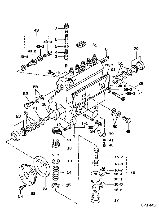
| 000. | [01] | 09010-03881 | BODY ASSY, INJECTI | ME029131 |
| 001. | [01] | 19011-02770 | HOUSING KIT, INJEC | ME703937 |
| 001-001. | [03] | 94904-30010 | BOLT, STUD | ME702091 |
| 003. | [06] | 09015-00030 | ELEMENT SUB-ASSY, | ME022597 |
| 004. | [06] | 09014-00061 | VALVE SUB-ASSY, IN | 90140-0061 |
| 005. | [06] | 09013-70010 | GASKET, DELIVERY V | ME022084 |
| 006. | [06] | 09013-60040 | SPRING, DELIVERY V | ME022617 |
| 007. | [06] | 09013-10010 | HOLDER, DELIVERY V | ME022081 |
| 008. | [01] | 09021-20130 | RACK, CONTROL | ME728838 |
| 009. | [01] | 09021-50060 | SCREW, RACK GUIDE | ME728163 |
| 010. | [06] | 09016-10160 | SLEEVE, PLUNGER CO | ME022134 |
| 010. | [06] | 09016-10330 | SLEEVE, PLUNGER CO | ME702060 |
| 011. | [06] | 09015-60010 | PINION, PLUNGER CO | ME702058 |
| 012. | [06] | 09015-70010 | SCREW, PLUNGER CON | ME702059 |
| 013. | [06] | 09016-30010 | SEAT, SPRING, UPR | ME702061 |
| 013. | [06] | 09016-30191 | SEAT, SPRING, UPR | ME736080 |
| 014. | [06] | 09016-40010 | SPRING, PUMP PLUNG | ME702062 |
| 015. | [06] | 09016-50010 | SEAT, SPRING, LWR | ME702063 |
| 016. | [06] | 09017-00130 | TAPPET SUB-ASSY,IN | ME702064 |
| 016-001. | [06] | 09016-90130 | BODY, INJECTION PU | ME702065 |
| 016-001. | [06] | 09017-10173 | TAPPET, INJECTION | |
| 016-002. | [06] | 09017-30010 | BOLT, INJECTION PU | ME702066 |
| 016-003. | [06] | 09017-40010 | NUT, INJECTION PUM | ME702067 |
| 016-004. | [06] | 09017-60010 | PIN, INJECTION PUM | ME702068 |
| 016-005. | [06] | 09017-80030 | BUSHING, INJECTION | ME702069 |
| 016-006. | [06] | 09018-10030 | ROLLER, INJECTION | ME702070 |
| 016-007. | [06] | 09017-50040 | SLIDER | ME736247 |
| 017. | [06] | 09018-90090 | PLUG, INJECTION PU | ME703276 |
| 018. | [01] | 09019-10152 | CAMSHAFT, INJECTIO | ME022137 |
| 020. | [02] | 94910-10120 | BEARING, ROLLER | ME702096 |
| 021. | [02] | 09019-30020 | RING, CAMSHAFT ADJ | ME702074 |
| 023. | [01] | 09020-10300 | COVER, BEARING | ME728839 |
| 024. | [01] | 09020-60160 | GASKET, BEARING CO | ME728820 |
| 024. | [01] | 09020-60010 | GASKET, BEARING CO | ME703584 |
| 025. | [03] | 90258-06001 | WASHER, SPRING | ME702596 |
| 029. | [01] | 09027-00941 | COVER SUB-ASSY, IN | ME703939 |
| 029. | [01] | 09027-00622 | COVER SUB-ASSY, IN | 09027-00621 |
| 029-002. | [02] | 09027-60030 | SCREW | ME703028 |
| 029-003. | [02] | 09024-30030 | PACKING, AIR BLEED | ME702057 |
| 029-006. | [01] | 09027-50083 | PROCESSING DRAWING | ME702602 |
| 029-007. | [01] | 09027-20220 | GASKET, INJECTION | ME702085 |
| 031. | [03] | 09023-00031 | PLATE SET, VALVE H | ME702082 |
| 034. | [03] | 90160-06051 | NUT, HEXAGON | ME702588 |
| 039. | [01] | 09036-10040 | BEARING, CENTER | ME702088 |
| 040. | [02] | 91050-05351 | SCREW, CROSSRECESS | ME702597 |
| 040. | [02] | 94900-66550 | SCREW | ME736044 |
| 041. | [02] | 94901-81030 | WASHER, COPPER PLA | ME702094 |
| 043. | [01] | 09024-00010 | BLEEDER SUB-ASSY, | ME702083 |
| 043-001. | [01] | 09024-10010 | WASHER, AIR BLEEDE | ME702102 |
| 043-002. | [01] | 09024-20010 | NIPPLE, AIR BLEEDE | ME022094 |
| 043-003. | [01] | 09024-30030 | PACKING, AIR BLEED | ME702057 |
| 043-004. | [01] | 09024-40010 | SCREW, AIR BLEEDER | MM501930 |
| 047. | [01] | 94914-00380 | O-RING | ME702097 |
| 048. | [01] | 94918-00060 | SCREW, HOLLOW | ME702598 |
| 050. | [02] | 09025-10010 | WASHER, INJECTION | ME702595 |
| 051. | [6C] | 09019-40150 | PLATE, CAMSHAFT SH | ME703273 |
| 051. | [6C] | 09019-40140 | PLATE, CAMSHAFT SH | ME703272 |
| 051. | [6C] | 09019-40110 | PLATE, CAMSHAFT SH | ME703583 |
| 051. | [6C] | 09019-40060 | PLATE, CAMSHAFT SH | ME022103 |
| 051. | [6C] | 09019-40050 | PLATE, CAMSHAFT SH | ME022102 |
| 051. | [6C] | 09019-40040 | PLATE, CAMSHAFT SH | ME022101 |
| 051. | [6C] | 09019-40030 | PLATE, CAMSHAFT SH | ME022100 |
| 051. | [6C] | 09019-40020 | PLATE, CAMSHAFT SH | ME022099 |
| 051. | [6C] | 09019-40010 | PLATE, CAMSHAFT SH | ME702075 |
| 052. | [01] | 94918-00310 | SCREW, HOLLOW | ME702236 |
| 053. | [02] | 09022-20070 | WASHER, FUEL PIPE | ME702217 |
| 054. | [04] | 94904-71360 | BOLT, W/WASHER | ME022507 |
Include in #3:
Cross reference number
| Part num | Firm num | Firm | Name |
| 09010-03881 | ME029131 | BODY ASSY, INJECTI |
Information:
Adjustment Of Engine
Inspection and Adjustment of Valve Clearance
Inspect and adjust valve clearance when the engine is cold. (1) Inspecting valve clearance(a) Inspect the valve clearance in the firing order by turning the crankshaft 240° in the normal direction to bring each piston to the top dead center on the compression stroke. (b) Attach a socket and ratchet handle to the crankshaft pulley tightening nut, and turn the crankshaft.(c) When the No. 1 piston is at the top dead center on the compression stroke, the "0" line stamped on the circumference of the crankshaft pulley is aligned with the pointer of the timing gear case, and the inlet and exhaust valves are not lifted off their seats by the pushrods. (d) Insert a feeler gage between the rocker arm and valve cap to inspect the clearance.
Checking top dead center cylinder of No. 1 piston compression stroke (1)
Checking top dead center cylinder of No. 1 piston compression stroke (2)(2) Adjusting valve clearance(a) Loosen the lock nut, insert a feeler gage between the rocker arm and valve cap, and while measuring the clearance, tighten or loosen the adjusting screw until the feeler gear moves slightly tight.(b) After adjusting the clearance, securely tighten the locknut, and inspect the clearance again.
Adjusting valve clearanceBleeding of Fuel Injection Pump
(1) Loosen the air vent plug of the fuel injection pump by about 1.5 turns.(2) Move up and down the priming pump cap.(3) Tighten the air vent plug when no air bubbles appear in the fuel coming out of it. Before tightening the last air vent plug, lock the priming pump cap of the fuel feed pump by turning it clockwise while pushing it down.(d) Bleed the right-hand fuel injection pump in the same way as the left-hand one. (a) If all the vent plugs are tightened before the priming pump cap is locked, the fuel pressure acts on the fuel feed pump to make it impossible to return the priming pump cap to the original position.(b) Thoroughly wipe off any fuel spilled from the air vent plugs with a cloth or the like.
Bleeding fuel injection pumpInspection of Fuel Injection Timing
The fuel injection timing varies with the output, speed and other engine specifications. Be sure to check it according to the specification sheet.(1) Checking top dead center of No.