Information body assy, injecti
Rating:
KIT List:
| Body assy, injecti | 1904400320 |
| Body assy, injecti | 1904400320 |
| Body assy, injecti | 1904400320 |
Scheme ###:
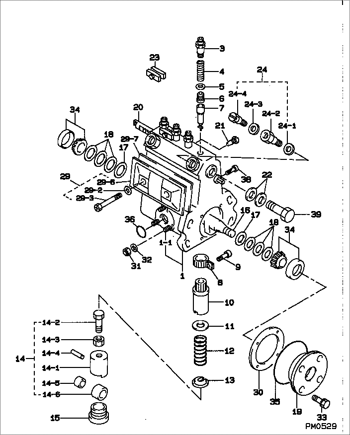
| 000. | [01] | 09010-03820 | BODY ASSY, INJECTI | 22120-87601-000 |
| 001. | [01] | 19011-01950 | HOUSING KIT, INJEC | 22190-87601-000 |
| 001-001. | [03] | 94904-30010 | BOLT, STUD | 90099-04071-000 |
| 003. | [04] | 09013-10010 | HOLDER, DELIVERY V | 22131-77020-000 |
| 004. | [04] | 09013-60050 | SPRING, DELIVERY V | 22148-46010-000 |
| 005. | [04] | 09013-70010 | GASKET, DELIVERY V | 22149-76010-000 |
| 006. | [04] | 09014-00010 | VALVE SUB-ASSY, IN | 22104-77020-000 |
| 007. | [04] | 09015-01620 | ELEMENT SUB-ASSY, | 22105-87302-000 |
| 008. | [04] | 09015-60010 | PINION, PLUNGER CO | 22155-76010-000 |
| 009. | [04] | 09015-70010 | SCREW, PLUNGER CON | 22156-76010-000 |
| 010. | [04] | 09016-10160 | SLEEVE, PLUNGER CO | 22142-77020-000 |
| 010. | [04] | 09016-10330 | SLEEVE, PLUNGER CO | 22142-58230-000 |
| 011. | [04] | 09016-30010 | SEAT, SPRING, UPR | 22143-77020-000 |
| 011. | [04] | 09016-30191 | SEAT, SPRING, UPR | |
| 012. | [04] | 09016-40060 | SPRING, PUMP PLUNG | 22144-87301-000 |
| 013. | [04] | 09016-50010 | SEAT, SPRING, LWR | 22145-77020-000 |
| 014. | [04] | 09017-00130 | TAPPET SUB-ASSY,IN | |
| 014. | [04] | 09017-00020 | TAPPET SUB-ASSY,IN | 22106-77020-000 |
| 014-001. | [04] | 09016-90110 | BODY, INJECTION PU | 22139-67022-000 |
| 014-001. | [04] | 09016-90130 | BODY, INJECTION PU | |
| 014-001. | [04] | 09017-10173 | TAPPET, INJECTION | |
| 014-002. | [04] | 09017-30010 | BOLT, INJECTION PU | 22134-77020-000 |
| 014-003. | [04] | 09017-40010 | NUT, INJECTION PUM | 22135-77020-000 |
| 014-004. | [04] | 09017-60010 | PIN, INJECTION PUM | 09017-60010-000 |
| 014-005. | [04] | 09017-80010 | BUSHING, INJECTION | 09017-80010-000 |
| 014-005. | [04] | 09017-80030 | BUSHING, INJECTION | |
| 014-006. | [04] | 09018-10030 | ROLLER, INJECTION | |
| 014-006. | [04] | 09018-10010 | ROLLER, INJECTION | 09018-10010-000 |
| 014-007. | [04] | 09017-50040 | SLIDER | |
| 015. | [04] | 09018-90090 | PLUG, INJECTION PU | 22157-87302-000 |
| 016. | [01] | 09019-10082 | CAMSHAFT, INJECTIO | 22146-56010-000 |
| 017. | [02] | 09019-30020 | RING, CAMSHAFT ADJ | 22147-77020-000 |
| 018. | [6C] | 09019-40060 | PLATE, CAMSHAFT SH | 22166-76010-000 |
| 018. | [6C] | 09019-40050 | PLATE, CAMSHAFT SH | 22165-76010-000 |
| 018. | [6C] | 09019-40040 | PLATE, CAMSHAFT SH | 22164-76010-000 |
| 018. | [6C] | 09019-40030 | PLATE, CAMSHAFT SH | 22163-76010-000 |
| 018. | [6C] | 09019-40020 | PLATE, CAMSHAFT SH | 22162-76010-000 |
| 018. | [6C] | 09019-40010 | PLATE, CAMSHAFT SH | 22161-76010-000 |
| 019. | [01] | 09020-10390 | COVER, BEARING | 22111-87303-000 |
| 020. | [01] | 09021-20441 | RACK, CONTROL | 22114-48030-000 |
| 021. | [01] | 09021-50011 | SCREW, RACK GUIDE | 22115-77020-000 |
| 021. | [01] | 09021-50060 | SCREW, RACK GUIDE | 22115-78140-000 |
| 022. | [02] | 09022-20070 | WASHER, FUEL PIPE | 90042-10015-000 |
| 023. | [02] | 09023-00031 | PLATE SET, VALVE H | 22102-77021-000 |
| 024. | [01] | 09024-00010 | BLEEDER SUB-ASSY, | 22150-67010-000 |
| 024-001. | [01] | 09024-10010 | WASHER, AIR BLEEDE | 22393-87301-000 |
| 024-002. | [01] | 09024-20010 | NIPPLE, AIR BLEEDE | 22118-77020-000 |
| 024-003. | [01] | 09024-30030 | PACKING, AIR BLEED | 22121-77020-000 |
| 024-004. | [01] | 09024-40010 | SCREW, AIR BLEEDER | 22117-77020-000 |
| 029. | [01] | 09027-01090 | COVER SUB-ASSY, IN | 22103-48030-000 |
| 029-002. | [02] | 09024-30030 | PACKING, AIR BLEED | 22121-77020-000 |
| 029-003. | [02] | 09027-60030 | SCREW | |
| 029-006. | [01] | 09027-50182 | PROCESSING DRAWING | 22563-78050-000 |
| 029-007. | [01] | 09027-20210 | GASKET, INJECTION | 22153-78030-000 |
| 030. | [01] | 09020-60060 | GASKET, BEARING CO | 22195-68010-000 |
| 030. | [01] | 09020-60170 | GASKET, BEARING CO | |
| 031. | [03] | 90160-06051 | NUT, HEXAGON | 94110-40600-000 |
| 032. | [03] | 90258-06001 | WASHER, SPRING | 94511-00600-000 |
| 033. | [04] | 91418-06201 | BOLT, W/WASHER | 91611-60620-000 |
| 034. | [02] | 94910-10120 | BEARING, ROLLER | 90099-10087-000 |
| 035. | [01] | 94914-00970 | O-RING | 90043-01039-000 |
| 036. | [01] | 94914-00380 | O-RING | 90099-14015-000 |
| 038. | [01] | 94918-00570 | SCREW, HOLLOW | |
| 039. | [01] | 94918-00310 | SCREW, HOLLOW | 90099-18010-000 |
Include in #3:
Cross reference number
| Part num | Firm num | Firm | Name |
| 09010-03820 | 22120-8760 | BODY ASSY, INJECTI | |
| 22120-87601-000 | DAIHATSU | BODY ASSY, INJECTI |
Information:
Introduction
Do not perform any of the following procedure or order parts until you have read and understand the procedure. The procedure that follows below covers that installation of the new Diesel Exhaust Fluid (DEF) filter.Required Parts
Table 1 below contain the parts needed to complete the installation of the new DEF filter.Note: Only one DEF filter group is required per engine. Use Table 2 to determine which filter is the appropriate filter for each DEF header. Illustration 1 shows the location of the DEF header part number.
Table 1
Item Qty Part Number Part Description
1 1 452-6055 Filter Base As
2 1 453-1604(1) Diesel Exhaust Fluid Filter Gp
3 1 453-1605***#i05999309/d1820e940*** Diesel Exhaust Fluid Filter Gp
4 1 453-1606***#i05999309/d1820e940*** Diesel Exhaust Fluid Filter Gp
5 1 378-3187 Diesel Exhaust Fluid Filter Gp
6 1 423-3251 Connector
7 1 425-0385 Filter As
8 1 391-5262 Gasket
(1) Use Table 2 to choose the correct part that corresponds to the DEF header
Illustration 1 g03745839
(1) Location of DEF header part number
Table 2
DEF Header Part Number Required DEF Filter
434-3241 453-1604
434-3242 453-1605
434-3243 453-1606 Installation Procedure
Illustration 2 g03736523
(1) DEF header
(2) DEF filter
(3) DEF tank
(4) DEF header bolts
Clean the area around DEF header (1). Clear any dirt or debris that could contaminate the DEF tank or lines when removed. Note: If proper cleaning is not performed, DEF pump performance issues or failure may occur.
Disconnect the two DEF lines, two coolant lines, and harness from the DEF header assembly.
Remove the six DEF header screws (4) from the DEF header assembly. Note: Do not discard the screws that secure the DEF header assembly to the DEF tank. The screws will be reused in a later step.
Remove the DEF header assembly. Remove the previous DEF header gasket and discard.
Illustration 3 g03736534
(5) 452-6055 Filter Base As
Install filter base assembly (5) onto the DEF header assembly. Note: Each half of the adapter has two small locking tabs that secure to the bottom side of the DEF header assembly.
Remove the previous 425-0385 Filter As located at the bottom of the DEF pick-up tube.
Install the new 425-0385 Filter As onto the DEF header assembly.
Illustration 4 g03736545
(6) Band clamp
Install the correct DEF filter onto the DEF header adapter and secure using band clamp (6) that is supplied. Torque the band clamp to 4.5 0.7 N m (40 6 lb in).
Install the DEF header assembly back into the DEF tank. Secure the DEF header to the DEF tank using the six screws previously removed in Step 3. Torque the six screws to 5 1 N m (44 9 lb in).
Reconnect the harness, coolant lines, and DEF lines to the DEF header.