Information body assy, injecti

Rating:
Scheme ###:
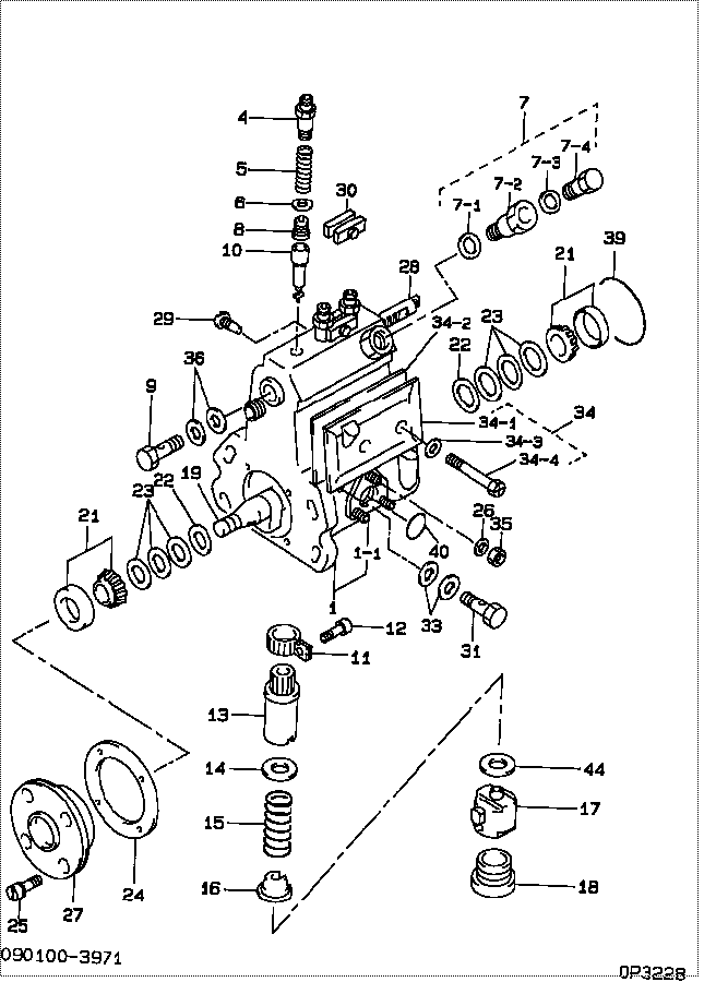
| 000. | [01] | 09010-03601 | BODY ASSY, INJECTI | |
| 001. | [01] | 19011-02031 | HOUSING KIT, INJEC | |
| 001-001. | [01] | 94904-30010 | BOLT, STUD | 85265-00057 |
| 004. | [03] | 09013-10010 | HOLDER, DELIVERY V | 09013-10010 |
| 004. | [03] | 09013-10540 | HOLDER, DELIVERY V | |
| 005. | [03] | 09013-60040 | SPRING, DELIVERY V | 09013-60040 |
| 006. | [03] | 09013-70010 | GASKET, DELIVERY V | 85265-00019 |
| 007. | [01] | 09024-00010 | BLEEDER SUB-ASSY, | 09024-00010 |
| 007. | [02] | 09024-00010 | BLEEDER SUB-ASSY, | 09024-00010 |
| 007-001. | [01] | 09024-10010 | WASHER, AIR BLEEDE | MM500486 |
| 007-002. | [01] | 09024-20010 | NIPPLE, AIR BLEEDE | 85265-00013 |
| 007-003. | [01] | 09024-30030 | PACKING, AIR BLEED | 85265-00016 |
| 007-004. | [01] | 09024-40010 | SCREW, AIR BLEEDER | 09024-40010 |
| 008. | [03] | 09014-00061 | VALVE SUB-ASSY, IN | 85265-00072 |
| 009. | [01] | 94918-00310 | SCREW, HOLLOW | 85265-00078 |
| 010. | [03] | 09015-00350 | ELEMENT SUB-ASSY, | 09015-00350 |
| 011. | [03] | 09015-60010 | PINION, PLUNGER CO | 85265-00074 |
| 012. | [03] | 09015-70010 | SCREW, PLUNGER CON | 85265-00027 |
| 013. | [03] | 09016-10160 | SLEEVE, PLUNGER CO | 85265-00073 |
| 013. | [03] | 09016-10330 | SLEEVE, PLUNGER CO | |
| 014. | [03] | 09016-30010 | SEAT, SPRING, UPR | 09016-30010 |
| 014. | [03] | 09016-30191 | SEAT, SPRING, UPR | |
| 015. | [03] | 09016-40090 | SPRING, PUMP PLUNG | 09016-40090 |
| 016. | [03] | 09016-50160 | SEAT, SPRING, LWR | 09016-50160 |
| 017. | [03] | 09017-00070 | TAPPET SUB-ASSY,IN | 09017-00070 |
| 018. | [03] | 09018-90090 | PLUG, INJECTION PU | 09018-90090 |
| 018. | [03] | 09018-90060 | PLUG, INJECTION PU | 85265-00075 |
| 019. | [01] | 09019-10201 | CAMSHAFT, INJECTIO | 09019-10200 |
| 021. | [02] | 94910-10120 | BEARING, ROLLER | 94910-10121 |
| 022. | [02] | 09019-30020 | RING, CAMSHAFT ADJ | 09019-30020 |
| 023. | [6C] | 09019-40150 | PLATE, CAMSHAFT SH | |
| 023. | [6C] | 09019-40140 | PLATE, CAMSHAFT SH | |
| 023. | [6C] | 09019-40060 | PLATE, CAMSHAFT SH | 09019-40060 |
| 023. | [6C] | 09019-40050 | PLATE, CAMSHAFT SH | 09019-40050 |
| 023. | [6C] | 09019-40040 | PLATE, CAMSHAFT SH | 09019-40040 |
| 023. | [6C] | 09019-40030 | PLATE, CAMSHAFT SH | 09019-40030 |
| 023. | [6C] | 09019-40020 | PLATE, CAMSHAFT SH | 09019-40020 |
| 023. | [6C] | 09019-40010 | PLATE, CAMSHAFT SH | 09019-40010 |
| 024. | [01] | 09020-60160 | GASKET, BEARING CO | |
| 024. | [01] | 09020-60010 | GASKET, BEARING CO | 09020-60010 |
| 025. | [04] | 94904-71360 | BOLT, W/WASHER | 94904-71360 |
| 026. | [03] | 90258-06001 | WASHER, SPRING | 90258-06001 |
| 027. | [01] | 09020-10300 | COVER, BEARING | 09020-10300 |
| 028. | [01] | 09021-20050 | RACK, CONTROL | EZ40057028 |
| 029. | [01] | 09021-50060 | SCREW, RACK GUIDE | 09021-50060 |
| 029. | [01] | 09021-50011 | SCREW, RACK GUIDE | 09021-50011 |
| 030. | [02] | 09023-00031 | PLATE SET, VALVE H | 85265-00052 |
| 031. | [01] | 94918-00690 | SCREW, HOLLOW | |
| 033. | [02] | 09025-10010 | WASHER, INJECTION | 85265-00077 |
| 034. | [01] | 09027-00520 | COVER SUB-ASSY, IN | |
| 034. | [01] | 09027-01140 | COVER SUB-ASSY, IN | |
| 034. | [01] | 09027-01150 | COVER SUB-ASSY, IN | |
| 034-001. | [01] | 09027-50133 | PROCESSING DRAWING | |
| 034-002. | [01] | 09027-20200 | GASKET, INJECTION | |
| 034-003. | [02] | 09024-30030 | PACKING, AIR BLEED | 85265-00016 |
| 034-004. | [02] | 09027-60030 | SCREW | |
| 035. | [03] | 90160-06051 | NUT, HEXAGON | 85265-00085 |
| 036. | [02] | 09022-20070 | WASHER, FUEL PIPE | 85265-00079 |
| 039. | [01] | 94914-00060 | O-RING | 85265-00061 |
| 040. | [01] | 94914-00380 | O-RING | 85265-00084 |
| 044. | [ C] | 09031-10090 | PLATE, TAPPET ADJU | 09031-10090 |
| 044. | [ C] | 09031-10100 | PLATE, TAPPET ADJU | 09031-10100 |
| 044. | [ C] | 09031-10110 | PLATE, TAPPET ADJU | 09031-10110 |
| 044. | [ C] | 09031-10120 | PLATE, TAPPET ADJU | 09031-10120 |
| 044. | [ C] | 09031-10130 | PLATE, TAPPET ADJU | 09031-10130 |
| 044. | [ C] | 09031-10140 | PLATE, TAPPET ADJU | 09031-10140 |
| 044. | [ C] | 09031-10080 | PLATE, TAPPET ADJU | 09031-10080 |
| 044. | [ C] | 09031-10070 | PLATE, TAPPET ADJU | 09031-10070 |
| 044. | [ C] | 09031-10060 | PLATE, TAPPET ADJU | 09031-10060 |
| 044. | [ C] | 09031-10050 | PLATE, TAPPET ADJU | 09031-10050 |
| 044. | [ C] | 09031-10040 | PLATE, TAPPET ADJU | 09031-10040 |
| 044. | [ C] | 09031-10030 | PLATE, TAPPET ADJU | 09031-10030 |
| 044. | [ C] | 09031-10020 | PLATE, TAPPET ADJU | 09031-10020 |
| 044. | [ C] | 09031-10010 | PLATE, TAPPET ADJU | 09031-10010 |
| 044. | [ C] | 09031-10150 | PLATE, TAPPET ADJU | 09031-10150 |
Include in #3:
Cross reference number
| Part num | Firm num | Firm | Name |
| 09010-03601 | BODY ASSY, INJECTI |
Information:
Serviceable Parts
The parts that are required to convert the unit injector pump to the new restriction orifice are included in 229-5103 Orifice Kit . The parts that are included with this kit are listed in Table 1.
Table 1
Part Number Part Name Quantity
229-5119 Orifice Assembly 1
9M-4704 Bolt 1
REHS1469 "Installation of New Restriction Orifice for the Unit Injector Pump" 1 Installation Procedure
Note: Reuse existing O-rings and seals.Note: Oil may leak from the unit injector pump when the compensator housing and the housing for the pump control are removed. It may be necessary to use shop towels in order to absorb any leakage.
Place shop towels below the unit injector pump in order to absorb any leakage.
Illustration 1 g00929119
Unit Injector Pump
Remove the four bolts (1) that secure the compensator housing and the housing for the pump control.
Remove the compensator housing (2) and the housing for the pump control (3). This will expose the restriction orifice (4) .Note: Identify the location of the O-ring seals in the housings for reassembly.
Thread the installation tool 9M-4704 Bolt into the restriction orifice (4) at least three turns. Grip the installation tool with pliers. Remove the restriction orifice from the unit injector pump.
Thread the installation tool 9M-4704 Bolt into the threaded end of the new 229-5119 Orifice Assembly at least three turns. Press the new restriction orifice into the bore. Installation is complete when the restriction orifice reaches the bottom of the bore. Remove the installation tool from the restriction orifice.
Install the housing for the pump control. Install the compensator housing. Insert the four bolts and tighten to 7 N m (62 lb in).Note: Take care in order to ensure that the O-ring seals are not omitted or damaged during reassembly.
Turn on the engine. Allow coolant temperature to reach 80° 10°C (176° 18°F). Check for leaks from the unit injector pump.
Connect the electronic service tool to the ECM in order to monitor the rail pressure.
Unplug the rail pressure control valve. Crank the engine. Monitor the rail pressure.Note: The engine may start if the rail pressure control valve is set to the proper pressure. If the rail pressure is 5.4 0.6 MPa (783 87 psi), no pump adjustment is necessary.
If the rail pressure does not meet the required pressure of 5.4 0.6 MPa (783 87 psi), refer to Special Instruction, REHS0282, "Installation Procedure Of The HEUI Pump Compensator Standby Plug For 3408E And 3412E Engines". Follow Steps 7, 8, and 9 in order to set the proper rail pressure.