Information body assy, injecti
Rating:
Scheme ###:
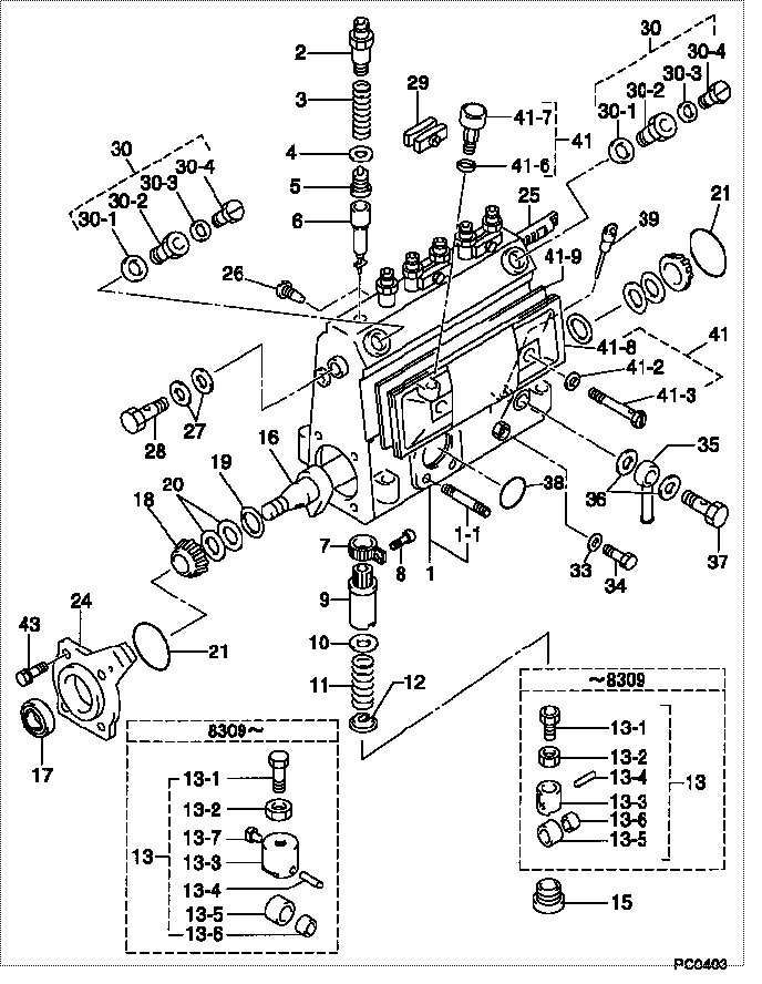
| 000. | [01] | 09010-03260 | BODY ASSY, INJECTI | 22110-1220 |
| 001. | [01] | 19011-01870 | HOUSING KIT, INJEC | 6 056 1200 10 |
| 001-001. | [03] | 94904-30010 | BOLT, STUD | 22857-1060A |
| 002. | [06] | 09013-10020 | HOLDER, DELIVERY V | 6 053 1250 60 |
| 003. | [06] | 09013-60070 | SPRING, DELIVERY V | 6 056 1200 30 |
| 004. | [06] | 09013-70010 | GASKET, DELIVERY V | 22847-1450 |
| 005. | [06] | 09014-00010 | VALVE SUB-ASSY, IN | 2210E-77020 |
| 006. | [06] | 09015-00350 | ELEMENT SUB-ASSY, | 22104-1370 |
| 007. | [06] | 09015-60010 | PINION, PLUNGER CO | 22128-1020A |
| 008. | [06] | 09015-70010 | SCREW, PLUNGER CON | 22865-1280A |
| 009. | [06] | 09016-10330 | SLEEVE, PLUNGER CO | 22118-1310A |
| 010. | [06] | 09016-30191 | SEAT, SPRING, UPR | 22119-1190A |
| 011. | [06] | 09016-40010 | SPRING, PUMP PLUNG | 6 056 1200 80 |
| 012. | [06] | 09016-50010 | SEAT, SPRING, LWR | 22122-1060 |
| 013. | [06] | 09017-00020 | TAPPET SUB-ASSY,IN | 2210G-77020 |
| 013. | [06] | 09017-00130 | TAPPET SUB-ASSY,IN | 22105-1260 |
| 013-001. | [06] | 09017-30010 | BOLT, INJECTION PU | 0901H-30010 |
| 013-002. | [06] | 09017-40010 | NUT, INJECTION PUM | 6 053 1252 40 |
| 013-003. | [06] | 09017-10173 | TAPPET, INJECTION | |
| 013-003. | [06] | 09016-90130 | BODY, INJECTION PU | 22145-1010 |
| 013-003. | [06] | 09016-90110 | BODY, INJECTION PU | 6 306 1205 20 |
| 013-004. | [06] | 09017-60010 | PIN, INJECTION PUM | 22105-1130 |
| 013-005. | [06] | 09018-10010 | ROLLER, INJECTION | 22105-1140 |
| 013-005. | [06] | 09018-10030 | ROLLER, INJECTION | |
| 013-006. | [06] | 09017-80010 | BUSHING, INJECTION | 22105-1150 |
| 013-006. | [06] | 09017-80030 | BUSHING, INJECTION | |
| 013-007. | [06] | 09017-50040 | SLIDER | 6 306 1205 40 |
| 015. | [06] | 09018-90090 | PLUG, INJECTION PU | 22845-1420A |
| 016. | [01] | 09019-10021 | CAMSHAFT, INJECTIO | 22123-1210 |
| 017. | [01] | 94915-01750 | SEAL, OIL | 22823-1220 |
| 018. | [02] | 94910-10120 | BEARING, ROLLER | 22837-1230A |
| 019. | [02] | 09019-30020 | RING, CAMSHAFT ADJ | 22124-1160A |
| 020. | [6C] | 09019-40150 | PLATE, CAMSHAFT SH | 22129-1200A |
| 020. | [6C] | 09019-40140 | PLATE, CAMSHAFT SH | 22129-1190A |
| 020. | [6C] | 09019-40060 | PLATE, CAMSHAFT SH | 22885-4950A |
| 020. | [6C] | 09019-40050 | PLATE, CAMSHAFT SH | 22885-4940A |
| 020. | [6C] | 09019-40040 | PLATE, CAMSHAFT SH | 22885-4930A |
| 020. | [6C] | 09019-40030 | PLATE, CAMSHAFT SH | 22885-4920A |
| 020. | [6C] | 09019-40020 | PLATE, CAMSHAFT SH | 22885-4910A |
| 020. | [6C] | 09019-40010 | PLATE, CAMSHAFT SH | 22885-4900A |
| 021. | [02] | 94914-00060 | O-RING | 22813-1280 |
| 024. | [01] | 09020-10053 | COVER, BEARING | 6 053 1257 10 |
| 025. | [01] | 09021-20010 | RACK, CONTROL | 22113-1320A |
| 026. | [01] | 09021-50060 | SCREW, RACK GUIDE | 22811-4850A |
| 027. | [02] | 09022-20070 | WASHER, FUEL PIPE | 0 902 2200 70 |
| 027. | [02] | 09022-20011 | WASHER, FUEL PIPE | 22873-1240 |
| 028. | [01] | 94918-00310 | SCREW, HOLLOW | S2283-51310-A |
| 029. | [03] | 09023-00031 | PLATE SET, VALVE H | 22109-1090A |
| 030. | [02] | 09024-00010 | BLEEDER SUB-ASSY, | 22106-1060 |
| 030-001. | [02] | 09024-10010 | WASHER, AIR BLEEDE | 22847-2150A |
| 030-002. | [02] | 09024-20010 | NIPPLE, AIR BLEEDE | 22873-1250 |
| 030-003. | [02] | 09024-30030 | PACKING, AIR BLEED | 22847-1890A |
| 030-004. | [02] | 09024-40010 | SCREW, AIR BLEEDER | 2211H-77020 |
| 033. | [01] | 09024-80010 | WASHER, DRAIN SCRE | 22847-1730A |
| 034. | [01] | 09024-90010 | SCREW, DRAIN | 6 053 1266 20 |
| 035. | [01] | 09025-00020 | NIPPLE SUB-ASSY, O | 6 056 1325 60 |
| 036. | [02] | 94901-02470 | WASHER | 22847-1900A |
| 037. | [01] | 94918-00060 | SCREW, HOLLOW | 22835-1110A |
| 037. | [01] | 94918-00600 | SCREW, HOLLOW | 22835-1100 |
| 038. | [01] | 94914-00380 | O-RING | 22817-1540A |
| 039. | [01] | 09029-00330 | GAUGE SUB-ASSY, IN | 22112-1110 |
| 041. | [01] | 09027-00561 | COVER SUB-ASSY, IN | 22102-1050A |
| 041-002. | [02] | 09024-30030 | PACKING, AIR BLEED | 22847-1890A |
| 041-003. | [02] | 09027-60030 | SCREW | 22815-1550A |
| 041-006. | [01] | 09024-10010 | WASHER, AIR BLEEDE | 22847-2150A |
| 041-007. | [01] | 09028-00040 | CLEANER, INJECTION | 0 902 8000 40 |
| 041-008. | [01] | 09027-10201 | PLATE, INJECTION P | |
| 041-009. | [01] | 09027-20220 | GASKET, INJECTION | 22847-2180A |
| 043. | [04] | 94904-71360 | BOLT, W/WASHER | 22815-2500A |
Include in #3:
Cross reference number
| Part num | Firm num | Firm | Name |
| 09010-03260 | 22110-1220 | BODY ASSY, INJECTI | |
| 22110-1220 | HINO | BODY ASSY, INJECTI |
Information:
General Information
Fig. 1-Fuel Pump LocationThe fuel transfer pump is located on the right side of the engine as shown on (1, Fig. 1).Removal
Disconnect and plug fuel lines (2, Fig. 1) at pump.Remove attaching hardware.Repair
Airtex Fuel Transfer Pumps
Fig. 2-Airtex Fuel Transfer PumpTo remove or install primer lever, (1, Fig. 2) compress rocker arm lever (2). And pull primer lever out.Further disassembly of the transfer pump is not possible.A.C. Fuel Transfer Pumps
When disassembling, mark pump cover and pump body for easier reassembly.Test all parts for serviceability and replace, if necessary.When assembling the fuel pump, observe the following:
Fig. 3-A.C. Fuel Transfer PumpMake sure diaphragm (1, Fig. 3) is engaged in rocker arm (2).Before installing the pump cover (3), position diaphragm so that it is level by moving rocker arm. Hold lever in this position.Install pump cover and cover screws. However, turn in screws so that they just contact the washers. Operate rocker arm several times, then release with a snap to make sure that diaphragm will not be overstretched when in use. Tighten cover screws in a crosswise pattern.Corona (B.C.D.) Fuel Transfer Pump
When disassembling, mark pump cover and pump body for easier reassembly.
Fig. 4-Diaphragm RemovalDisconnect diaphragm by pressing it against flange (Fig. 4).
Fig. 5-Remove Valve Plate and FilterCarefully remove valve plate with filter from pump cover (Fig. 5).Check all parts for serviceability and replace, if necessary.When assembling the fuel pump, observe the following: Make sure diaphragm is engaged in rocker arm.Before installing the pump cover, position diaphragm so that it is level by moving rocker arm. Hold lever in this position.Install pump cover and cover screws. However, turn in screws so that they just contact the washers.Operate rocker arm several times, then release with a snap to make sure that diaphragm will not be overstretched when in use.Tighten cover screws in a crosswise pattern.Installation
Using a new gasket, attach transfer pump to cylinder block. Connect lines and bleed fuel system.