Information body assy, injecti
Rating:
KIT List:
| Body assy, injecti | 1904400340 |
| Body assy, injecti | 1904400340 |
| Body assy, injecti | 1904400340 |
Scheme ###:
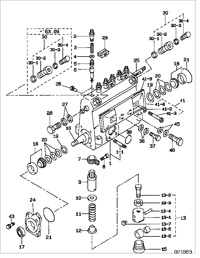
| 000. | [01] | 09010-03120 | BODY ASSY, INJECTI | 22130-1020 |
| 001. | [01] | 19011-01670 | HOUSING KIT, INJEC | 22101-1180 |
| 001. | [01] | 19011-01420 | HOUSING KIT, INJEC | 22101-1030 |
| 001-001. | [03] | 94904-30010 | BOLT, STUD | 22857-1060A |
| 002. | [06] | 09013-10020 | HOLDER, DELIVERY V | 6 053 1250 60 |
| 003. | [06] | 09013-60070 | SPRING, DELIVERY V | 6 056 1200 30 |
| 004. | [06] | 09013-70010 | GASKET, DELIVERY V | 22847-1450 |
| 005. | [06] | 09014-00510 | VALVE SUB-ASSY, IN | 22103-1290 |
| 006. | [06] | 09015-01450 | ELEMENT SUB-ASSY, | 22104-1020A |
| 007. | [06] | 09015-60010 | PINION, PLUNGER CO | 22128-1020A |
| 008. | [06] | 09015-70010 | SCREW, PLUNGER CON | 22865-1280A |
| 009. | [06] | 09016-10160 | SLEEVE, PLUNGER CO | 22118-1090A |
| 009. | [06] | 09016-10330 | SLEEVE, PLUNGER CO | 22118-1310A |
| 010. | [06] | 09016-30010 | SEAT, SPRING, UPR | 2214D-77020 |
| 010. | [06] | 09016-30191 | SEAT, SPRING, UPR | 22119-1190A |
| 011. | [06] | 09016-40010 | SPRING, PUMP PLUNG | 6 056 1200 80 |
| 012. | [06] | 09016-50010 | SEAT, SPRING, LWR | 22122-1060 |
| 013. | [06] | 09017-00020 | TAPPET SUB-ASSY,IN | 2210G-77020 |
| 013. | [06] | 09017-00130 | TAPPET SUB-ASSY,IN | 22105-1260 |
| 013-001. | [06] | 09017-10173 | TAPPET, INJECTION | |
| 013-001. | [06] | 09016-90130 | BODY, INJECTION PU | 22145-1010 |
| 013-001. | [06] | 09016-90110 | BODY, INJECTION PU | 6 306 1205 20 |
| 013-002. | [06] | 09017-30010 | BOLT, INJECTION PU | 0901H-30010 |
| 013-003. | [06] | 09017-40010 | NUT, INJECTION PUM | 6 053 1252 40 |
| 013-004. | [06] | 09017-60010 | PIN, INJECTION PUM | 22105-1130 |
| 013-005. | [06] | 09017-80030 | BUSHING, INJECTION | |
| 013-006. | [06] | 09018-10030 | ROLLER, INJECTION | |
| 013-007. | [06] | 09017-50040 | SLIDER | 6 306 1205 40 |
| 015. | [06] | 09018-90060 | PLUG, INJECTION PU | 22845-1160A |
| 015. | [06] | 09018-90090 | PLUG, INJECTION PU | 22845-1420A |
| 016. | [01] | 09019-10021 | CAMSHAFT, INJECTIO | 22123-1210 |
| 017. | [01] | 94915-00050 | SEAL, OIL | 22823-1110 |
| 017. | [01] | 94915-01750 | SEAL, OIL | 22823-1220 |
| 018. | [02] | 94910-10120 | BEARING, ROLLER | 22837-1230A |
| 019. | [02] | 09019-30020 | RING, CAMSHAFT ADJ | 22124-1160A |
| 020. | [6C] | 09019-40150 | PLATE, CAMSHAFT SH | 22129-1200A |
| 020. | [6C] | 09019-40140 | PLATE, CAMSHAFT SH | 22129-1190A |
| 020. | [6C] | 09019-40060 | PLATE, CAMSHAFT SH | 22885-4950A |
| 020. | [6C] | 09019-40050 | PLATE, CAMSHAFT SH | 22885-4940A |
| 020. | [6C] | 09019-40040 | PLATE, CAMSHAFT SH | 22885-4930A |
| 020. | [6C] | 09019-40030 | PLATE, CAMSHAFT SH | 22885-4920A |
| 020. | [6C] | 09019-40020 | PLATE, CAMSHAFT SH | 22885-4910A |
| 020. | [6C] | 09019-40010 | PLATE, CAMSHAFT SH | 22885-4900A |
| 021. | [02] | 94914-00060 | O-RING | 22813-1280 |
| 024. | [01] | 09020-10053 | COVER, BEARING | 6 053 1257 10 |
| 025. | [01] | 09021-20010 | RACK, CONTROL | 22113-1320A |
| 026. | [01] | 09021-50011 | SCREW, RACK GUIDE | 22811-1980A |
| 026. | [01] | 09021-50060 | SCREW, RACK GUIDE | 22811-4850A |
| 027. | [02] | 09022-20070 | WASHER, FUEL PIPE | 0 902 2200 70 |
| 027. | [02] | 94901-02490 | WASHER | 22877-1100A |
| 027. | [02] | 09022-20011 | WASHER, FUEL PIPE | 22873-1240 |
| 028. | [01] | 94918-00310 | SCREW, HOLLOW | 22835-1310A |
| 029. | [03] | 09023-00031 | PLATE SET, VALVE H | 22109-1090A |
| 030. | [02] | 09024-00010 | BLEEDER SUB-ASSY, | 22106-1060 |
| 030. | [01] | 09024-00010 | BLEEDER SUB-ASSY, | 22106-1060 |
| 030-001. | [02] | 09024-10010 | WASHER, AIR BLEEDE | 22847-2150A |
| 030-001. | [01] | 09024-10010 | WASHER, AIR BLEEDE | 22847-2150A |
| 030-002. | [01] | 09024-20010 | NIPPLE, AIR BLEEDE | 22873-1250 |
| 030-002. | [02] | 09024-20010 | NIPPLE, AIR BLEEDE | 22873-1250 |
| 030-003. | [02] | 09024-30030 | PACKING, AIR BLEED | 22847-1890A |
| 030-003. | [01] | 09024-30030 | PACKING, AIR BLEED | 22847-1890A |
| 030-004. | [02] | 09024-40010 | SCREW, AIR BLEEDER | 2211H-77020 |
| 030-004. | [01] | 09024-40010 | SCREW, AIR BLEEDER | 2211H-77020 |
| 036. | [02] | 94901-02470 | WASHER | 22847-1900A |
| 036. | [02] | 09025-10010 | WASHER, INJECTION | 22865-1290A |
| 037. | [01] | 94918-00060 | SCREW, HOLLOW | 22835-1110A |
| 038. | [01] | 94914-00380 | O-RING | 22817-1540A |
| 041. | [01] | 09027-00622 | COVER SUB-ASSY, IN | 22170-1690A |
| 041. | [01] | 09027-00941 | COVER SUB-ASSY, IN | 22102-1010 |
| 041-002. | [02] | 09024-30030 | PACKING, AIR BLEED | 22847-1890A |
| 041-003. | [02] | 09027-60030 | SCREW | 22815-1550A |
| 041-008. | [01] | 09027-50083 | PROCESSING DRAWING | 22127-1220A |
| 041-009. | [01] | 09027-20220 | GASKET, INJECTION | 22847-2180A |
| 043. | [04] | 94904-71360 | BOLT, W/WASHER | 22815-2500A |
| 045. | [02] | 94901-81120 | WASHER, COPPER PLA | 22847-1760A |
| 045. | [02] | 94901-02500 | WASHER | 22847-1920A |
| 046. | [01] | 94918-00420 | SCREW, HOLLOW | 22835-1180A |
Include in #3:
Cross reference number
| Part num | Firm num | Firm | Name |
| 09010-03120 | 22130-1020 | BODY ASSY, INJECTI | |
| 22130-1020 | HINO | BODY ASSY, INJECTI |
Information:
Illustration 1 g00564355
7W-2743 Electronic Speed Switch (ESS)
(1) Push button for Overspeed Verification
(2) Reset button
(3) Overspeed indicator lamp
(4) Seal screw plug for adjusting the engine overspeed
(5) Seal screw plug for adjusting the crank terminate speed
(6) Seal screw plug for adjusting the oil step pressure speed setting The oil step speed calibration increases the oil step speed setting or the oil step speed calibration decreases the oil step speed setting. Refer to the Speed Specification Chart in order to find the oil step speed that is equal to the engine rpm when the engine is running.
Remove the lockwire and the seal from seal screw plug (6). Remove seal screw plug (6) from the access hole for the oil step speed adjusting screw.
Use a small screwdriver to lightly turn the oil step speed adjusting screw in the direction of the "MAX" arrow or the clockwise direction. Turn the screw twenty times. The oil step speed adjusting screw will vary the setting of a potentiometer that is inside of the ESS. The oil step speed adjusting screw will not cause damage to the potentiometer. Also, the screw can not be removed if the screw is turned in the wrong direction.
Connect a voltmeter with the positive lead at terminal (ESS-13) and the negative lead at (ESS-5). Use a 6V-7070 Digital Multimeter or a voltmeter with the same accuracy. Measure the voltage.
For a specific engine rating, find the engine rpm in the column for the oil step speed setting in the Speed Specification Chart. Run the engine at the rpm that is specified in the table.
While the engine is running, look into the hole for the adjustment of the oil step speed. A red indicator lamp should be lighted. A positive voltage should be observed on the multimeter 9 seconds after the indicator lamp is lighted. Turn the oil step speed adjusting screw clockwise until the indicator lamp turns off. The oil step speed setting is above the present rpm of the engine. Slowly turn the oil step speed adjusting screw counterclockwise until the indicator lamp is lighted. After a 9 second delay, a positive voltage should be observed on the multimeter. This position is the correct setting for the oil step speed.
Install seal screw plug (6) in the access hole for the oil step speed adjusting screw. Tighten the screw to a torque of 0.20 0.03 N m (1.8 .3 lb in). Install the lockwire and the seal if the overspeed calibration and the crank terminate speed calibration are also complete.