Information body assy, injecti
Rating:
Scheme ###:
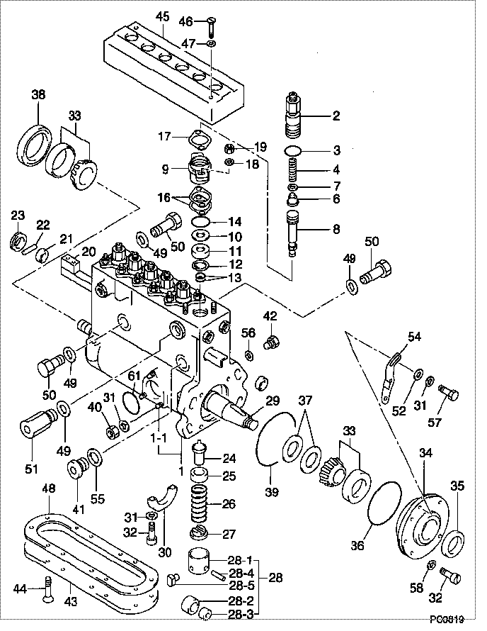
| 000. | [01] | 09010-03080 | BODY ASSY, INJECTI | |
| 001. | [01] | 09011-01660 | HOUSING SUB-ASSY, | |
| 001-001. | [03] | 94904-30010 | BOLT, STUD | |
| 002. | [06] | 09013-10360 | HOLDER, DELIVERY V | |
| 003. | [06] | 94914-02710 | O-RING | |
| 004. | [06] | 09013-60350 | SPRING, DELIVERY V | |
| 006. | [06] | 09014-00680 | VALVE SUB-ASSY, IN | |
| 007. | [06] | 94901-00670 | WASHER | |
| 008. | [06] | 09015-01700 | ELEMENT SUB-ASSY, | |
| 009. | [06] | 09042-00010 | HOLDER ASSY, ELMEN | |
| 010. | [06] | 94901-34340 | WASHER, PLATE, SK | |
| 011. | [06] | 09043-60030 | COVER, ELEMENT | |
| 012. | [06] | 94907-20780 | RING, SNAP | |
| 013. | [12] | 94914-01120 | O-RING | |
| 013. | [12] | 09013-90170 | O-RING | |
| 014. | [06] | 94914-00991 | O-RING | |
| 016. | [ C] | 09043-80540 | SHIM, ELEMENT HOLD | |
| 016. | [ C] | 09043-80530 | SHIM, ELEMENT HOLD | |
| 016. | [ C] | 09043-80060 | SHIM, ELEMENT HOLD | |
| 016. | [ C] | 09043-80050 | SHIM, ELEMENT HOLD | |
| 016. | [ C] | 09043-80040 | SHIM, ELEMENT HOLD | |
| 016. | [ C] | 09043-80030 | SHIM, ELEMENT HOLD | |
| 016. | [ C] | 09043-80020 | SHIM, ELEMENT HOLD | |
| 016. | [ C] | 09043-80010 | SHIM, ELEMENT HOLD | |
| 017. | [06] | 09043-20010 | PLATE, DELIVERY VA | |
| 018. | [12] | 90258-10001 | WASHER, SPRING | |
| 019. | [12] | 90160-10081 | NUT, HEXAGON | |
| 020. | [01] | 09021-00330 | RACK ASSY, CONTROL | |
| 021. | [02] | 09011-40060 | BUSHING, CONTROL R | |
| 022. | [01] | 94908-20290 | PIN, STRAIGHT | |
| 023. | [01] | 09036-70010 | BUSHING, CONTROL R | |
| 024. | [06] | 09016-00020 | SLEEVE SUB-ASSY, C | |
| 024. | [06] | 09016-00130 | SLEEVE SUB-ASSY, C | |
| 025. | [06] | 09016-30060 | SEAT, SPRING, UPR | |
| 026. | [06] | 09016-40130 | SPRING, PUMP PLUNG | |
| 027. | [06] | 09016-50041 | SEAT, SPRING, LWR | |
| 028. | [06] | 09017-00110 | TAPPET SUB-ASSY,IN | |
| 028-001. | [06] | 09017-10131 | TAPPET, INJECTION | |
| 028-002. | [06] | 09018-10170 | ROLLER, INJECTION | |
| 028-003. | [06] | 09017-80060 | BUSHING, INJECTION | |
| 028-004. | [06] | 09017-60080 | PIN, INJECTION PUM | |
| 028-005. | [06] | 09017-50040 | SLIDER | |
| 029. | [01] | 09019-10540 | CAMSHAFT, INJECTIO | |
| 030. | [01] | 09036-10070 | BEARING, CENTER | |
| 031. | [07] | 90258-06001 | WASHER, SPRING | |
| 032. | [06] | 90015-06181 | SCREW, SLOTTED OVA | |
| 033. | [02] | 94910-10130 | BEARING, ROLLER | |
| 034. | [01] | 09020-10290 | COVER, BEARING | |
| 035. | [01] | 94915-01420 | SEAL, OIL | |
| 035. | [01] | 94915-02820 | SEAL, OIL | |
| 036. | [01] | 94914-03940 | O-RING | |
| 037. | [2C] | 09020-80140 | PLATE, SHIM | |
| 037. | [2C] | 09020-80130 | PLATE, SHIM | |
| 037. | [2C] | 09020-80120 | PLATE, SHIM | |
| 037. | [2C] | 09020-80110 | PLATE, SHIM | |
| 037. | [2C] | 09020-80100 | PLATE, SHIM | |
| 037. | [2C] | 09020-80090 | PLATE, SHIM | |
| 037. | [2C] | 09020-80080 | PLATE, SHIM | |
| 038. | [01] | 09043-30010 | RETAINER, BEARING | |
| 039. | [01] | 94914-02720 | O-RING | |
| 040. | [03] | 90160-06051 | NUT, HEXAGON | |
| 041. | [01] | 09031-70070 | PLUG, SCREW | |
| 042. | [06] | 09031-70060 | PLUG, SCREW | |
| 043. | [01] | 09027-10340 | PLATE, INJECTION P | |
| 043. | [01] | 09027-10380 | PLATE, INJECTION P | |
| 044. | [12] | 90045-06121 | SCREW, SLOTTED POL | |
| 045. | [01] | 09043-10031 | COVER, DELIVERY VA | |
| 046. | [02] | 90060-06351 | SCREW, CROSSRECESS | |
| 047. | [02] | 09140-30110 | WASHER, LOCK | |
| 048. | [01] | 09027-20140 | GASKET, INJECTION | |
| 048. | [01] | 09027-20260 | GASKET, INJECTION | |
| 049. | [04] | 94901-80550 | WASHER, COPPER PLA | |
| 050. | [03] | 09022-40021 | SCREW,PLUG | |
| 051. | [01] | 09031-00100 | VALVE ASSY, OVERFL | |
| 052. | [02] | 90200-06241 | WASHER, PLATE | |
| 054. | [01] | 09011-80050 | NEEDLE, TIMING | |
| 055. | [01] | 94901-80710 | WASHER, COPPER PLA | |
| 056. | [06] | 94901-81500 | WASHER, COPPER PLA | |
| 057. | [02] | 94900-20350 | SCREW, COUNTERSUNK | |
| 058. | [04] | 94901-50740 | WASHER, SPRING | |
| 061. | [01] | 94914-00380 | O-RING |
Include in #3:
09010-03080
as BODY ASSY, INJECTI
Cross reference number
| Part num | Firm num | Firm | Name |
| 09010-03080 | BODY ASSY, INJECTI |
Information:
Description of Electrical System Symbols And Codes
The Point-To-Point graphical system is used in all the wiring diagrams and schematics which help describe the systems operation and troubleshooting of the ETR/ETS electric protection system.Each wire in the wiring harness is heat stamped the length of the wire with the wire number code as shown in the ETR/ETS Wiring Using Wire Number Codes diagram on Illustration 7. The first number pair of the wiring code identifies the terminal on an engine component to which one end of the wire should be attached. The second number pair of the wiring code identifies the terminal on the component to which the other end of the wire should be attached. The number assigned to each terminal of each component will be the same for all engine models.The two numbers in the wiring code differentiate between left and right hand mounting. Illustration 2 contains the Number Codes and an example of usage.The symbols for the engine components will be the same for all 3200-3500 Series Engines.The use of abbreviations, symbols, and codes is provided by the following example. In order to locate and identify the wire which connects the starting motor magnetic switch and the starting motor, first determine the correct drawing abbreviation. The Abbreviation List on Illustration 1 shows ("SMMS") as the abbreviation symbol for the starting motor magnetic switch. ("SM") is shown as the abbreviation symbol for the starting motor. The symbols for both the starting motor magnetic switch and the starting motor are listed under the Starting System on 3.Locate the ("SMMS") and ("SM") symbols on the Starting System list on Illustration 3. Because an engine option exists for two starting motors which requires two starting motor magnetic switches, symbols for ("SMMS 1"), ("SMMS 2"), ("SM 1"), and ("SM 2") are shown under the Starting System list. If the engine has only one starting motor, only refer to ("SMMS 1") and ("SM 1").The Number Code list on Illustration 2shows that for a component in the starting system a wire number of 050 through 099 is a right hand (RH) usage. A wire number of 150 through 199 is a left hand usage (LH).The ("SMMS 1") out terminal is designated ("056") (RH) or ("156") (LH). The lower terminal on ("SM 1") is designated ("052") (RH) or ("152") (LH). On ETR/ETS Wiring Using Wire Number Codes diagram on Illustration 7, the wire connecting ("SMMS 1") and ("SM 1") is coded ("052-056 OR 152-156"). This wire connects the ("SMMS 1") and ("SM 1"). The other wire connected to the same terminal point on ("SMMS 1") is coded ("056-127 OR 127-156"). This code indicates that one end of the wire is connected to the ("SMMS 1") out terminal and the other end of the wire is connected to terminal 27 ("TS-27") on the terminal strip.
Illustration 1 g00291427
ETR/ETS Component And Wire Color Code Abbreviations
Illustration 2 g00291428
ETR/ETS Number And Letter Codes, Wire Sizes, And Electric Governor Control Terminals
Illustration 3 g00291448
ETR/ETS Starting And Charging Systems Symbols
Illustration 4 g00291449
ETR/ETS Monitoring And Control Systems