Information body assy, injecti
Rating:
Scheme ###:
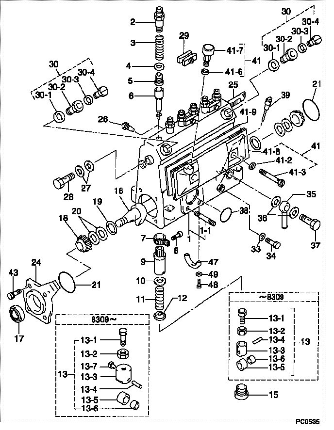
| 000. | [01] | 09010-02791 | BODY ASSY, INJECTI | |
| 001. | [01] | 09010-90602 | HOUSING SUB-ASSY, | 22101-1510 |
| 001-001. | [03] | 94904-30010 | BOLT, STUD | 22857-1060A |
| 002. | [06] | 09013-10020 | HOLDER, DELIVERY V | 6 053 1250 60 |
| 003. | [06] | 09013-60110 | SPRING, DELIVERY V | 22125-1070 |
| 004. | [06] | 09013-70010 | GASKET, DELIVERY V | 22847-1450 |
| 005. | [06] | 09014-00021 | VALVE SUB-ASSY, IN | 22103-1210 |
| 006. | [06] | 09015-00680 | ELEMENT SUB-ASSY, | 22104-1380 |
| 007. | [06] | 09015-60010 | PINION, PLUNGER CO | 22128-1020A |
| 008. | [06] | 09015-70010 | SCREW, PLUNGER CON | 22865-1280A |
| 009. | [06] | 09016-10330 | SLEEVE, PLUNGER CO | 22118-1310A |
| 010. | [06] | 09016-30010 | SEAT, SPRING, UPR | 2214D-77020 |
| 011. | [06] | 09016-40010 | SPRING, PUMP PLUNG | 6 056 1200 80 |
| 012. | [06] | 09016-50010 | SEAT, SPRING, LWR | 22122-1060 |
| 013. | [06] | 09017-00020 | TAPPET SUB-ASSY,IN | 2210G-77020 |
| 013. | [06] | 09017-00130 | TAPPET SUB-ASSY,IN | 22105-1260 |
| 013-001. | [06] | 09017-30010 | BOLT, INJECTION PU | 0901H-30010 |
| 013-002. | [06] | 09017-40010 | NUT, INJECTION PUM | 6 053 1252 40 |
| 013-003. | [06] | 09017-10173 | TAPPET, INJECTION | |
| 013-003. | [06] | 09016-90130 | BODY, INJECTION PU | 22145-1010 |
| 013-003. | [06] | 09016-90110 | BODY, INJECTION PU | 6 306 1205 20 |
| 013-004. | [06] | 09017-60010 | PIN, INJECTION PUM | 22105-1130 |
| 013-005. | [06] | 09018-10010 | ROLLER, INJECTION | 22105-1140 |
| 013-005. | [06] | 09018-10030 | ROLLER, INJECTION | |
| 013-006. | [06] | 09017-80010 | BUSHING, INJECTION | 22105-1150 |
| 013-006. | [06] | 09017-80030 | BUSHING, INJECTION | |
| 013-007. | [06] | 09017-50040 | SLIDER | 6 306 1205 40 |
| 015. | [06] | 09018-90090 | PLUG, INJECTION PU | 22845-1420A |
| 016. | [01] | 09019-10220 | CAMSHAFT, INJECTIO | 22160-1020 |
| 017. | [01] | 94915-01750 | SEAL, OIL | 22823-1220 |
| 018. | [02] | 94910-10120 | BEARING, ROLLER | 22837-1230A |
| 019. | [02] | 09019-30020 | RING, CAMSHAFT ADJ | 22124-1160A |
| 020. | [6C] | 09019-40150 | PLATE, CAMSHAFT SH | 22129-1200A |
| 020. | [6C] | 09019-40140 | PLATE, CAMSHAFT SH | 22129-1190A |
| 020. | [6C] | 09019-40060 | PLATE, CAMSHAFT SH | 22885-4950A |
| 020. | [6C] | 09019-40050 | PLATE, CAMSHAFT SH | 22885-4940A |
| 020. | [6C] | 09019-40040 | PLATE, CAMSHAFT SH | 22885-4930A |
| 020. | [6C] | 09019-40030 | PLATE, CAMSHAFT SH | 22885-4920A |
| 020. | [6C] | 09019-40020 | PLATE, CAMSHAFT SH | 22885-4910A |
| 020. | [6C] | 09019-40010 | PLATE, CAMSHAFT SH | 22885-4900A |
| 021. | [02] | 94914-00060 | O-RING | 22813-1280 |
| 024. | [01] | 09020-10053 | COVER, BEARING | 6 053 1257 10 |
| 025. | [01] | 09021-20010 | RACK, CONTROL | 22113-1320A |
| 026. | [01] | 09021-50060 | SCREW, RACK GUIDE | 22811-4850A |
| 027. | [02] | 94901-02490 | WASHER | 22877-1100A |
| 028. | [01] | 94918-00310 | SCREW, HOLLOW | 22835-1310A |
| 029. | [03] | 09023-00031 | PLATE SET, VALVE H | 22109-1090A |
| 030. | [02] | 09024-00010 | BLEEDER SUB-ASSY, | 22106-1060 |
| 030-001. | [02] | 09024-10010 | WASHER, AIR BLEEDE | 22847-2150A |
| 030-002. | [02] | 09024-20010 | NIPPLE, AIR BLEEDE | 22873-1250 |
| 030-003. | [02] | 09024-30030 | PACKING, AIR BLEED | 22847-1890A |
| 030-004. | [02] | 09024-40010 | SCREW, AIR BLEEDER | 2211H-77020 |
| 033. | [01] | 09024-80010 | WASHER, DRAIN SCRE | 22847-1730A |
| 034. | [01] | 09024-90010 | SCREW, DRAIN | 6 053 1266 20 |
| 035. | [01] | 09025-00071 | NIPPLE SUB-ASSY, O | |
| 036. | [02] | 94901-02490 | WASHER | 22877-1100A |
| 037. | [01] | 94918-00060 | SCREW, HOLLOW | 22835-1110A |
| 037. | [01] | 94918-00600 | SCREW, HOLLOW | 22835-1100 |
| 038. | [01] | 94914-00380 | O-RING | 22817-1540A |
| 039. | [01] | 09029-00330 | GAUGE SUB-ASSY, IN | 22112-1110 |
| 041. | [01] | 09027-00930 | COVER SUB-ASSY, IN | |
| 041-002. | [02] | 09024-30030 | PACKING, AIR BLEED | 22847-1890A |
| 041-003. | [02] | 09027-60030 | SCREW | 22815-1550A |
| 041-006. | [01] | 09024-10010 | WASHER, AIR BLEEDE | 22847-2150A |
| 041-007. | [01] | 09028-00060 | CLEANER, INJECTION | 0 902 8000 60 |
| 041-008. | [01] | 09027-10201 | PLATE, INJECTION P | |
| 041-009. | [01] | 09027-20220 | GASKET, INJECTION | 22847-2180A |
| 043. | [04] | 94904-71360 | BOLT, W/WASHER | 22815-2500A |
| 047. | [01] | 09036-10060 | BEARING, CENTER | |
| 048. | [02] | 91050-05351 | SCREW, CROSSRECESS | 22815-2400A |
| 049. | [02] | 94901-81030 | WASHER, COPPER PLA | 22867-1020A |
Include in #3:
09000-09371
as BODY ASSY, INJECTI
09010-02791
Cross reference number
| Part num | Firm num | Firm | Name |
| 09010-02791 | BODY ASSY, INJECTI |
Information:
1. Determining Overhaul Timing
The timing of engine overhauls should be determined primarily in accordance with reductions in compression pressure. A reduction in compression pressure may be accompanied by one or more of the following externally observable symptoms:(a) Reduced power(b) Increased fuel consumption(c) Increased engine-oil consumption(d) Increased blowby gas through breather (possibly owing to wear on cylinder liners and piston rings)(e) Gas leakage (possibly owing to poor seating of intake and exhaust valves)(f) Starting problems(g) Increased engine noise(h) Abnormal exhaust-gas color after engine warmupAlthough these symptoms can be caused by a reduction in compression pressure, they can be caused also by other problems that are not related to engine deterioration. Notably, symptoms (b) and (f) may be affected significantly by the injection pump's injection rate, by the injection timing, by plunger wear, by injector defects, and/or by the battery, starter, and other electrical equipment. Symptoms (d) should be given special attention since a decrease in compression pressure owing to wear on the cylinder liners and piston rings is one of the most obvious signs that the engine needs an overhaul. It is essential, however, to measure the compression pressure in each cylinder and to use the results as the primary criteria for making a decision to overhaul the engine.2. Measuring Compression Pressure
2.1 Preparation for InspectionPerform the following checks before starting the inspection.(1) Make sure the engine oil, air cleaner, starter, and battery are normal.(2) Make sure the engine is warm.2.2 Inspection(1) Move the control lever to the stop position.(2) Remove all glow plugs, then connect the Compression Gauge Adapter (ST333060) and compression gauge to the cylinder whose compression pressure is to be checked.(3) Crank the engine using the starter until the needle of the compression gauge stops moving, then read the pressure indication.(4) If the measurement is lower than the specified limit, perform an overhaul.
(a) Measure the compression pressure of every cylinder. Measuring the compression pressures of two or three cylinders and simply assuming the compression pressures of the other cylinders is dangerous.(b) The compression pressure varies with the engine speed, so it is important to take all measurements with the same engine speed.
Unit: MPa {kgf/cm2} (psi) Take measurements with an engine speed of 240 min-1.
Compression gauge and adapter
Measuring compression pressure
(a) It is important to measure compression pressures regularly and to keep track of changes in them.(b) During the engine's run-in period and after an overhaul, the compression pressures will increase slightly as the piston rings, valve seats, and other parts fit snugly in position. The pressures will then decrease as parts wear.
3. Troubleshooting
3.1 OverviewDiesel-engine fault symptoms tend to have multiple causes, which influence each other. Consequently, it is often difficult to locate a fault based on the symptoms. Particular care is required when diagnosing faults related to the injection pump, injectors, and compression pressures since such faults may produce the same symptoms.For the above-mentioned reasons, the inspection sequences in the troubleshooting charts on the following pages start with items where the likelihood of a fault is greatest with