Information body assy, injecti
Rating:
Scheme ###:
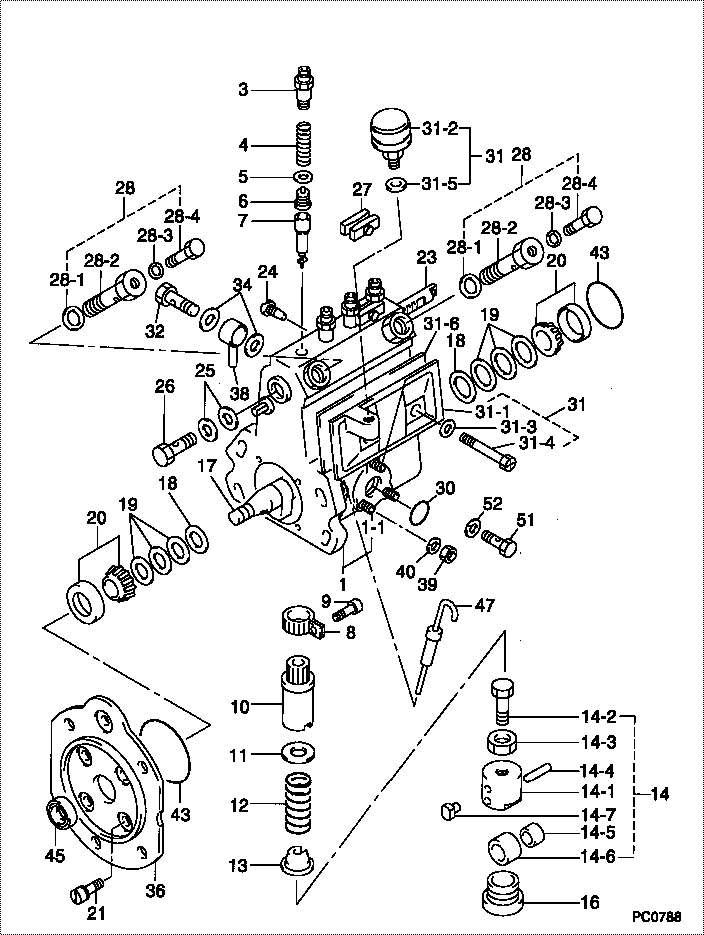
| 000. | [01] | 09010-02740 | BODY ASSY, INJECTI | MM500663 |
| 001. | [01] | 19011-00923 | HOUSING KIT, INJEC | MM501003 |
| 001-001. | [03] | 94904-30010 | BOLT, STUD | ME702091 |
| 003. | [04] | 09013-10010 | HOLDER, DELIVERY V | ME022081 |
| 004. | [04] | 09013-60010 | SPRING, DELIVERY V | MM500666 |
| 005. | [04] | 09013-70010 | GASKET, DELIVERY V | ME022084 |
| 006. | [04] | 09014-00010 | VALVE SUB-ASSY, IN | MM500669 |
| 007. | [04] | 09015-01460 | ELEMENT SUB-ASSY, | MM500672 |
| 008. | [04] | 09015-60010 | PINION, PLUNGER CO | ME702058 |
| 009. | [04] | 09015-70010 | SCREW, PLUNGER CON | ME702059 |
| 010. | [04] | 09016-10330 | SLEEVE, PLUNGER CO | ME702060 |
| 011. | [04] | 09016-30010 | SEAT, SPRING, UPR | ME702061 |
| 011. | [04] | 09016-30191 | SEAT, SPRING, UPR | ME736080 |
| 012. | [04] | 09016-40010 | SPRING, PUMP PLUNG | ME702062 |
| 013. | [04] | 09016-50010 | SEAT, SPRING, LWR | ME702063 |
| 014. | [04] | 09017-00020 | TAPPET SUB-ASSY,IN | |
| 014. | [04] | 09017-00130 | TAPPET SUB-ASSY,IN | ME702064 |
| 014-001. | [04] | 09017-10173 | TAPPET, INJECTION | |
| 014-001. | [04] | 09016-90130 | BODY, INJECTION PU | ME702065 |
| 014-001. | [04] | 09016-90110 | BODY, INJECTION PU | |
| 014-002. | [04] | 09017-30010 | BOLT, INJECTION PU | ME702066 |
| 014-003. | [04] | 09017-40010 | NUT, INJECTION PUM | ME702067 |
| 014-004. | [04] | 09017-60010 | PIN, INJECTION PUM | ME702068 |
| 014-005. | [04] | 09017-80010 | BUSHING, INJECTION | ME022126 |
| 014-005. | [04] | 09017-80030 | BUSHING, INJECTION | ME702069 |
| 014-006. | [04] | 09018-10010 | ROLLER, INJECTION | ME022127 |
| 014-006. | [04] | 09018-10030 | ROLLER, INJECTION | ME702070 |
| 014-007. | [04] | 09017-50040 | SLIDER | ME736247 |
| 016. | [04] | 09018-90090 | PLUG, INJECTION PU | ME703276 |
| 017. | [01] | 09019-10082 | CAMSHAFT, INJECTIO | MM500682 |
| 018. | [02] | 09019-30020 | RING, CAMSHAFT ADJ | ME702074 |
| 019. | [6C] | 09019-40290 | PLATE, CAMSHAFT SH | ME703274 |
| 019. | [6C] | 09019-40150 | PLATE, CAMSHAFT SH | ME703273 |
| 019. | [6C] | 09019-40140 | PLATE, CAMSHAFT SH | ME703272 |
| 019. | [6C] | 09019-40110 | PLATE, CAMSHAFT SH | ME703583 |
| 019. | [6C] | 09019-40060 | PLATE, CAMSHAFT SH | ME022103 |
| 019. | [6C] | 09019-40050 | PLATE, CAMSHAFT SH | ME022102 |
| 019. | [6C] | 09019-40040 | PLATE, CAMSHAFT SH | ME022101 |
| 019. | [6C] | 09019-40030 | PLATE, CAMSHAFT SH | ME022100 |
| 019. | [6C] | 09019-40020 | PLATE, CAMSHAFT SH | ME022099 |
| 019. | [6C] | 09019-40010 | PLATE, CAMSHAFT SH | ME702075 |
| 020. | [02] | 94910-10120 | BEARING, ROLLER | ME702096 |
| 021. | [04] | 94900-72471 | SCREW, W/WASHER | |
| 023. | [01] | 09021-20020 | RACK, CONTROL | MM500699 |
| 024. | [01] | 09021-50060 | SCREW, RACK GUIDE | ME728163 |
| 025. | [02] | 09022-20070 | WASHER, FUEL PIPE | ME702217 |
| 026. | [01] | 94918-00310 | SCREW, HOLLOW | ME702236 |
| 027. | [02] | 09023-00031 | PLATE SET, VALVE H | ME702082 |
| 028. | [02] | 09024-00010 | BLEEDER SUB-ASSY, | ME702083 |
| 028-001. | [02] | 09024-10010 | WASHER, AIR BLEEDE | ME702102 |
| 028-002. | [02] | 09024-20010 | NIPPLE, AIR BLEEDE | ME022094 |
| 028-003. | [02] | 09024-30030 | PACKING, AIR BLEED | ME702057 |
| 028-004. | [02] | 09024-40010 | SCREW, AIR BLEEDER | MM501930 |
| 030. | [01] | 94914-00380 | O-RING | ME702097 |
| 031. | [01] | 09027-00531 | COVER SUB-ASSY, IN | |
| 031-001. | [01] | 09027-10211 | PLATE, INJECTION P | |
| 031-002. | [01] | 09028-00040 | CLEANER, INJECTION | ME022089 |
| 031-003. | [02] | 09024-30030 | PACKING, AIR BLEED | ME702057 |
| 031-004. | [02] | 09027-60030 | SCREW | ME703028 |
| 031-005. | [01] | 09024-10010 | WASHER, AIR BLEEDE | ME702102 |
| 031-006. | [01] | 09027-20210 | GASKET, INJECTION | ME703052 |
| 032. | [01] | 94918-00600 | SCREW, HOLLOW | MM501002 |
| 034. | [02] | 09025-10010 | WASHER, INJECTION | ME702595 |
| 036. | [01] | 09020-40071 | FLANGE, INJECTION | MM500696 |
| 038. | [01] | 19025-00021 | PIPE ASSY, OVERFLO | 31661-13800 |
| 039. | [03] | 90160-06051 | NUT, HEXAGON | ME702588 |
| 040. | [03] | 90258-06001 | WASHER, SPRING | ME702596 |
| 043. | [02] | 94914-00060 | O-RING | MM500727 |
| 045. | [01] | 94915-00930 | SEAL, OIL | MM500905 |
| 047. | [01] | 09106-00080 | GAUGE SUB-ASSY, GO | ME022613 |
| 051. | [01] | 09024-90010 | SCREW, DRAIN | ME022112 |
| 052. | [01] | 09024-80010 | WASHER, DRAIN SCRE | ME702175 |
Include in #3:
09000-08332
as BODY ASSY, INJECTI
09010-02740
Cross reference number
| Part num | Firm num | Firm | Name |
| 09010-02740 | MM500663 | BODY ASSY, INJECTI | |
| MM500663 | MITSUBISHI | BODY ASSY, INJECTI |
Information:
GENERAL
1. Schematic <Solenoid ETS type> (1) Figure indicates a nominal size of automotive low-tension line (JIS C 3406).(2) This schematic shows the electrical system of the standard engine equipped with a key shut down solenoid and glow plugs.<Solenoid ETR type> (1) Figure indicates a nominal size of automotive low-tension line (JIS C 3406).(2) This schematic shows the electrical system of the standard engine equipped with a key shut down solenoid and glow plugs.2. Specifications (standard) STARTER
1. Disassembly
Disassembly sequence1 Pinion set2 Solenoid switch3 Rear bracket4 Brush holder5 Yoke6 Armature7 Ball bearing8 Ball9 Seal set10 Reduction gears11 Lever set12 Washer set13 Gear shaft14 Internal gear15 Overrunning clutch16 Front bracket
The pinion must be removed before removal or replacement of the following parts:a) Front bracketb) Reduction gearsc) Overrunning clutch
(1) Removing Pinion The pinion can be removed when it is held in the pushed-out position during energization of the solenoid switch. Disconnect the M-terminal connector and make a circuit that connects the starter motor and the battery as shown in the drawing. Close switches S1 and S2 to make the pinion come out and rotate. Then, open switch S2. The pinion will stop rotating but will stay in the pushed-out position. Apply a pipe-shaped implement to the pinion stopper and lightly tap it with a hammer to remove the pinion. If the pinion returns to the retracted position before disengagement of the stopper while the tool is being tapped, repeat the procedure from the beginning.(2) BallThe ball at the end of the armature acts as a bearing for movement of the armature in the thrust direction. When the armature is removed, the ball may stick to the grease on it. Be careful not to lose the ball.2. Inspection(1) Armature (a) Coil Short Circuit TestPlace the armature on a growler tester. Hold an iron rod parallel with the armature and slowly rotate the armature by hand. If the iron rod vibrates or is pulled toward the armature, the armature has a short-circuited coil and must be replaced.(b) Coil Ground TestCheck whether continuity exists between the commutator and shaft (or core). If continuity exists, the coil is grounded and the armature must be replaced. (c) Commutator Inspection1) Measure the commutator's runout using a dial gauge. If the measurement exceeds the specified limit, rectify the problem, making sure that the outside diameter stays within specification. If the surface is rough or has stepped wear, rectify the problem with emery paper (#300 - 500).
Unit: mm (in.) 2) Measure the commutator's outside diameter. If the measurement is out of specification, replace the armature.
Unit: mm (in.) 3) Measure the molding undercut depth between segments. If the depth is smaller than the limit, cut the molding to a depth of 0.4-0.6 mm (0.016-0.024 in.). (2) Field Coil (a) Coil Open Circuit TestCheck whether continuity exists between the terminal lead and each brush. If continuity does not exists, the field coil has an open circuit and the yoke assembly must be replaced. (b) Coil Ground TestCheck whether continuity exists between the