Information body assy, injecti
Rating:
Scheme ###:
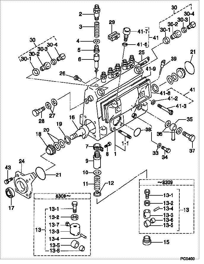
| 000. | [01] | 09010-02730 | BODY ASSY, INJECTI | |
| 001. | [01] | 09010-90031 | HOUSING SUB-ASSY, | 22101-1480 |
| 001-001. | [03] | 94904-30010 | BOLT, STUD | 22857-1060A |
| 002. | [06] | 09013-10020 | HOLDER, DELIVERY V | 6 053 1250 60 |
| 003. | [06] | 09013-60010 | SPRING, DELIVERY V | 2214J-76020 |
| 004. | [06] | 09013-70010 | GASKET, DELIVERY V | 22847-1450 |
| 005. | [06] | 09014-00010 | VALVE SUB-ASSY, IN | 2210E-77020 |
| 006. | [06] | 09015-01000 | ELEMENT SUB-ASSY, | 22104-1540 |
| 007. | [06] | 09015-60010 | PINION, PLUNGER CO | 22128-1020A |
| 008. | [06] | 09015-70010 | SCREW, PLUNGER CON | 22865-1280A |
| 009. | [06] | 09016-10330 | SLEEVE, PLUNGER CO | 22118-1310A |
| 010. | [06] | 09016-30010 | SEAT, SPRING, UPR | 2214D-77020 |
| 011. | [06] | 09016-40010 | SPRING, PUMP PLUNG | 6 056 1200 80 |
| 012. | [06] | 09016-50010 | SEAT, SPRING, LWR | 22122-1060 |
| 013. | [06] | 09017-00020 | TAPPET SUB-ASSY,IN | 2210G-77020 |
| 013. | [06] | 09017-00130 | TAPPET SUB-ASSY,IN | 22105-1260 |
| 013-001. | [06] | 09017-30010 | BOLT, INJECTION PU | 0901H-30010 |
| 013-002. | [06] | 09017-40010 | NUT, INJECTION PUM | 6 053 1252 40 |
| 013-003. | [06] | 09017-10173 | TAPPET, INJECTION | |
| 013-003. | [06] | 09016-90130 | BODY, INJECTION PU | 22145-1010 |
| 013-003. | [06] | 09016-90110 | BODY, INJECTION PU | 6 306 1205 20 |
| 013-004. | [06] | 09017-60010 | PIN, INJECTION PUM | 22105-1130 |
| 013-005. | [06] | 09018-10010 | ROLLER, INJECTION | 22105-1140 |
| 013-005. | [06] | 09018-10030 | ROLLER, INJECTION | |
| 013-006. | [06] | 09017-80010 | BUSHING, INJECTION | 22105-1150 |
| 013-006. | [06] | 09017-80030 | BUSHING, INJECTION | |
| 013-007. | [06] | 09017-50040 | SLIDER | 6 306 1205 40 |
| 015. | [06] | 09018-90090 | PLUG, INJECTION PU | 22845-1420A |
| 016. | [01] | 09019-10021 | CAMSHAFT, INJECTIO | 22123-1210 |
| 017. | [01] | 94915-01750 | SEAL, OIL | 22823-1220 |
| 018. | [02] | 94910-10120 | BEARING, ROLLER | 22837-1230A |
| 019. | [02] | 09019-30020 | RING, CAMSHAFT ADJ | 22124-1160A |
| 020. | [6C] | 09019-40150 | PLATE, CAMSHAFT SH | 22129-1200A |
| 020. | [6C] | 09019-40140 | PLATE, CAMSHAFT SH | 22129-1190A |
| 020. | [6C] | 09019-40060 | PLATE, CAMSHAFT SH | 22885-4950A |
| 020. | [6C] | 09019-40050 | PLATE, CAMSHAFT SH | 22885-4940A |
| 020. | [6C] | 09019-40040 | PLATE, CAMSHAFT SH | 22885-4930A |
| 020. | [6C] | 09019-40030 | PLATE, CAMSHAFT SH | 22885-4920A |
| 020. | [6C] | 09019-40020 | PLATE, CAMSHAFT SH | 22885-4910A |
| 020. | [6C] | 09019-40010 | PLATE, CAMSHAFT SH | 22885-4900A |
| 021. | [02] | 94914-00060 | O-RING | 22813-1280 |
| 024. | [01] | 09020-10053 | COVER, BEARING | 6 053 1257 10 |
| 025. | [01] | 09021-20010 | RACK, CONTROL | 22113-1320A |
| 026. | [01] | 09021-50060 | SCREW, RACK GUIDE | 22811-4850A |
| 027. | [02] | 94901-02490 | WASHER | 22877-1100A |
| 028. | [01] | 94918-00310 | SCREW, HOLLOW | 22835-1310A |
| 029. | [03] | 09023-00031 | PLATE SET, VALVE H | 22109-1090A |
| 030. | [02] | 09024-00010 | BLEEDER SUB-ASSY, | 22106-1060 |
| 030-001. | [02] | 09024-10010 | WASHER, AIR BLEEDE | 22847-2150A |
| 030-002. | [02] | 09024-20010 | NIPPLE, AIR BLEEDE | 22873-1250 |
| 030-003. | [02] | 09024-30030 | PACKING, AIR BLEED | 22847-1890A |
| 030-004. | [02] | 09024-40010 | SCREW, AIR BLEEDER | 2211H-77020 |
| 033. | [01] | 09024-80010 | WASHER, DRAIN SCRE | 22847-1730A |
| 034. | [01] | 09024-90010 | SCREW, DRAIN | 6 053 1266 20 |
| 035. | [01] | 09025-00020 | NIPPLE SUB-ASSY, O | 6 056 1325 60 |
| 036. | [02] | 94901-02470 | WASHER | 22847-1900A |
| 037. | [01] | 94918-00060 | SCREW, HOLLOW | 22835-1110A |
| 037. | [01] | 94918-00600 | SCREW, HOLLOW | 22835-1100 |
| 038. | [01] | 94914-00380 | O-RING | 22817-1540A |
| 039. | [01] | 09029-00330 | GAUGE SUB-ASSY, IN | 22112-1110 |
| 041. | [01] | 09027-00840 | COVER SUB-ASSY, IN | 22102-1130 |
| 041-002. | [02] | 09024-30030 | PACKING, AIR BLEED | 22847-1890A |
| 041-003. | [02] | 09027-60030 | SCREW | 22815-1550A |
| 041-006. | [01] | 09024-10010 | WASHER, AIR BLEEDE | 22847-2150A |
| 041-007. | [01] | 09028-00040 | CLEANER, INJECTION | 0 902 8000 40 |
| 041-008. | [01] | 09027-10201 | PLATE, INJECTION P | |
| 041-009. | [01] | 09027-20220 | GASKET, INJECTION | 22847-2180A |
| 043. | [04] | 94904-71360 | BOLT, W/WASHER | 22815-2500A |
Include in #3:
09000-02285
as BODY ASSY, INJECTI
09010-02730
Cross reference number
| Part num | Firm num | Firm | Name |
| 09010-02730 | BODY ASSY, INJECTI |
Information:
Specifications
Structure And Operation
Cooling System (Flow of Coolant)
Thermostat
* The thermostat is a bottom bypass type that uses a wax-filled pellet as its flow-regulating element. When the wax is heated, it melts from solid to liquid, changing its total volume. This allows the valve to open or close in accordance with the coolant temperature, regulating and adjusting the flow of coolant to the radiator and to the cylinder head (bypassing the radiator).Water Pump
* The water pump has a drain hole to prevent coolant from entering the unit bearing in the case of defect of the unit seal.Troubleshooting
General Inspection And Adjustment
Inspection And Adjustment Of Belt Tension
* Make sure that there is no oil or grease on the belts. Belts soiled with oil or grease may easily slip, resulting in deteriorated performance of the cooling system.* The water pump pulley is driven by two belts. Always replace the two belts simultaneously to ensure that both belts have the same tension.
Service Standards (Unit: mm) Special Tools Inspection and Cleaning Procedure Inspection: Tension of belts * Press each belt at a central portion between pulleys with a force of approximately 98 N {10 kgf} as shown in the illustration and measure the amount of deflection of the belt.A: Crankshaft pulleyB: Water pump pulleyC: Alternator pulley* Place the small O-ring on
at the scale mark corresponding to 98N {10 kgf} (press force). * Place the large O-ring on
at the scale mark corresponding to the maximum permissible deflection value specified for the belt.* Place
at a central portion between pulleys of the belt and push the handle (indicated by the arrow in the illustration) until the O-ring touches the flange. *Measure the amount of deflection of the belt. * If the measured value deviates from the standard value range, adjust the tension of the belt as follows. Adjustment of belts * Loosen the alternator mounting bolt, and adjust the tension of the belt by moving the alternator as required.* After the adjustment is completed, retighten the mounting bolt firmly.
* Excessive tension in the belt may damage not only the belt itself but also the bearings of the related components.
Inspection of Belts
* Visually check the belts for possible cracks and damage. Belt replacement time varies depending on the severity of cracks and damage that may be found through the check. Study the table given below for the applicable replacement time. Coolant Replacement and Cleaning of Cooling System
Tightening Torque (Unit: N m {kgf m}) * Using the radiator for extended periods of time without cleaning can increase chance of rust and scale formation, which may cause engine overheating. The cooling system must be cleaned periodically.Draining of Coolant
* Opening the pressure cap while the coolant temperature is still high can cause hot coolant to spray out. Cover the pressure cap with a cloth, and loosen it slowly to let the pressure out before opening it fully.
* Drain the coolant only after it has cooled sufficiently to avoid getting scalded.
Cleaning Procedure
* Keep the coolant temperature at approximately 90°C so that the thermostat