Information body assy, injecti
Rating:
Scheme ###:
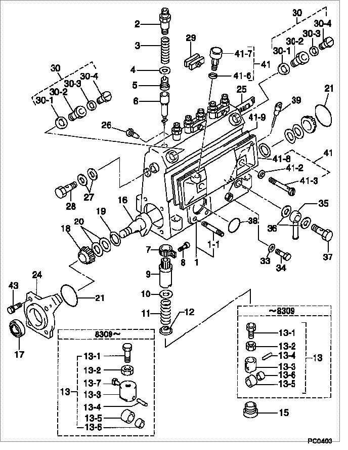
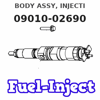
| 000. | [01] | 09010-02690 | BODY ASSY, INJECTI | |
| 001. | [01] | 09010-90031 | HOUSING SUB-ASSY, | 22101-1480 |
| 001-001. | [03] | 94904-30010 | BOLT, STUD | 22857-1060A |
| 002. | [06] | 09013-10020 | HOLDER, DELIVERY V | 6 053 1250 60 |
| 003. | [06] | 09013-60070 | SPRING, DELIVERY V | 6 056 1200 30 |
| 004. | [06] | 09013-70010 | GASKET, DELIVERY V | 22847-1450 |
| 005. | [06] | 09014-00560 | VALVE SUB-ASSY, IN | 22103-1070 |
| 006. | [06] | 09015-01000 | ELEMENT SUB-ASSY, | 22104-1540 |
| 007. | [06] | 09015-60010 | PINION, PLUNGER CO | 22128-1020A |
| 008. | [06] | 09015-70010 | SCREW, PLUNGER CON | 22865-1280A |
| 009. | [06] | 09016-10330 | SLEEVE, PLUNGER CO | 22118-1310A |
| 010. | [06] | 09016-30191 | SEAT, SPRING, UPR | 22119-1190A |
| 011. | [06] | 09016-40010 | SPRING, PUMP PLUNG | 6 056 1200 80 |
| 012. | [06] | 09016-50010 | SEAT, SPRING, LWR | 22122-1060 |
| 013. | [06] | 09017-00020 | TAPPET SUB-ASSY,IN | 2210G-77020 |
| 013. | [06] | 09017-00130 | TAPPET SUB-ASSY,IN | 22105-1260 |
| 013-001. | [06] | 09017-30010 | BOLT, INJECTION PU | 0901H-30010 |
| 013-002. | [06] | 09017-40010 | NUT, INJECTION PUM | 6 053 1252 40 |
| 013-003. | [06] | 09017-10173 | TAPPET, INJECTION | |
| 013-003. | [06] | 09016-90130 | BODY, INJECTION PU | 22145-1010 |
| 013-003. | [06] | 09016-90110 | BODY, INJECTION PU | 6 306 1205 20 |
| 013-004. | [06] | 09017-60010 | PIN, INJECTION PUM | 22105-1130 |
| 013-005. | [06] | 09018-10010 | ROLLER, INJECTION | 22105-1140 |
| 013-005. | [06] | 09018-10030 | ROLLER, INJECTION | |
| 013-006. | [06] | 09017-80010 | BUSHING, INJECTION | 22105-1150 |
| 013-006. | [06] | 09017-80030 | BUSHING, INJECTION | |
| 013-007. | [06] | 09017-50040 | SLIDER | 6 306 1205 40 |
| 015. | [06] | 09018-90090 | PLUG, INJECTION PU | 22845-1420A |
| 016. | [01] | 09019-10021 | CAMSHAFT, INJECTIO | 22123-1210 |
| 017. | [01] | 94915-01750 | SEAL, OIL | 22823-1220 |
| 018. | [02] | 94910-10120 | BEARING, ROLLER | 22837-1230A |
| 019. | [02] | 09019-30020 | RING, CAMSHAFT ADJ | 22124-1160A |
| 020. | [6C] | 09019-40150 | PLATE, CAMSHAFT SH | 22129-1200A |
| 020. | [6C] | 09019-40140 | PLATE, CAMSHAFT SH | 22129-1190A |
| 020. | [6C] | 09019-40060 | PLATE, CAMSHAFT SH | 22885-4950A |
| 020. | [6C] | 09019-40050 | PLATE, CAMSHAFT SH | 22885-4940A |
| 020. | [6C] | 09019-40040 | PLATE, CAMSHAFT SH | 22885-4930A |
| 020. | [6C] | 09019-40030 | PLATE, CAMSHAFT SH | 22885-4920A |
| 020. | [6C] | 09019-40020 | PLATE, CAMSHAFT SH | 22885-4910A |
| 020. | [6C] | 09019-40010 | PLATE, CAMSHAFT SH | 22885-4900A |
| 021. | [02] | 94914-00060 | O-RING | 22813-1280 |
| 024. | [01] | 09020-10053 | COVER, BEARING | 6 053 1257 10 |
| 025. | [01] | 09021-20010 | RACK, CONTROL | 22113-1320A |
| 026. | [01] | 09021-50060 | SCREW, RACK GUIDE | 22811-4850A |
| 027. | [02] | 94901-02490 | WASHER | 22877-1100A |
| 028. | [01] | 94918-00310 | SCREW, HOLLOW | 22835-1310A |
| 029. | [03] | 09023-00031 | PLATE SET, VALVE H | 22109-1090A |
| 030. | [02] | 09024-00010 | BLEEDER SUB-ASSY, | 22106-1060 |
| 030-001. | [02] | 09024-10010 | WASHER, AIR BLEEDE | 22847-2150A |
| 030-002. | [02] | 09024-20010 | NIPPLE, AIR BLEEDE | 22873-1250 |
| 030-003. | [02] | 09024-30030 | PACKING, AIR BLEED | 22847-1890A |
| 030-004. | [02] | 09024-40010 | SCREW, AIR BLEEDER | 2211H-77020 |
| 033. | [01] | 09024-80010 | WASHER, DRAIN SCRE | 22847-1730A |
| 034. | [01] | 09024-90010 | SCREW, DRAIN | 6 053 1266 20 |
| 035. | [01] | 09025-00071 | NIPPLE SUB-ASSY, O | |
| 036. | [02] | 94901-02470 | WASHER | 22847-1900A |
| 037. | [01] | 94918-00060 | SCREW, HOLLOW | 22835-1110A |
| 037. | [01] | 94918-00600 | SCREW, HOLLOW | 22835-1100 |
| 038. | [01] | 94914-00380 | O-RING | 22817-1540A |
| 039. | [01] | 09029-00330 | GAUGE SUB-ASSY, IN | 22112-1110 |
| 041. | [01] | 09027-00930 | COVER SUB-ASSY, IN | |
| 041-002. | [02] | 09024-30030 | PACKING, AIR BLEED | 22847-1890A |
| 041-003. | [02] | 09027-60030 | SCREW | 22815-1550A |
| 041-006. | [01] | 09024-10010 | WASHER, AIR BLEEDE | 22847-2150A |
| 041-007. | [01] | 09028-00060 | CLEANER, INJECTION | 0 902 8000 60 |
| 041-008. | [01] | 09027-10201 | PLATE, INJECTION P | |
| 041-009. | [01] | 09027-20220 | GASKET, INJECTION | 22847-2180A |
| 043. | [04] | 94904-71360 | BOLT, W/WASHER | 22815-2500A |
Include in #3:
09000-07981
as BODY ASSY, INJECTI
09010-02690
Cross reference number
| Part num | Firm num | Firm | Name |
| 09010-02690 | BODY ASSY, INJECTI |
Information:
Vertical Tachometer Drive
Removal
Fig. 1-Vertical Tachometer DriveRemove cap (1, Fig. 1). Lift gasket (2) out of adapter (3).Turn adapter counterclockwise to remove it. Remove aluminum washer (4). Lift pinion (5) out of flywheel housing (6).Repair
Inspect parts for damage. Replace damaged parts.Installation
Coat pinion with engine oil. Put pinion in flywheel housing so that end of pinion rests on machined pad (7) in flywheel housing. Make sure gear teeth on pinion engage teeth on drive gear. IMPORTANT: Adapter can be installed easily only if gears are in mesh.Put aluminum washer over bottom of adapter. Install adapter in flywheel housing. Tighten adapter securely.Flywheel
Removal
If engine is equipped with a clutch, remove the clutch (Group 4052).
Fig. 2-Flywheel Cap ScrewRemove two cap screws (1, Fig. 2) that hold flywheel on crankshaft. Install two pilot studs through flywheel into crankshaft. Tighten pilot studs securely.
Flywheel weighs 50 to 85 lb. (23 to 39 kg). Plan proper handling procedures to avoid injury.
Remove remaining cap screws (2) that hold flywheel on crankshaft.Install two of the cap screws removed in threaded holes in flywheel. Tighten cap screws evenly to push flywheel off crankshaft.Repair
If engine is equipped with a clutch, inspect clutch contact face on flywheel for scoring, overheating, and cracking.
Fig. 3-Flywheel ThicknessClutch contact face can be resurfaced if there is heat checking. Minimum thickness of flywheel at clutch contact face is: IMPORTANT: If heat checks or cracks can be seen after resurfacing flywheel to minimum thickness, install a new flywheel.Inspect ring gear for worn or broken teeth. If damaged, install a new one (Group 0433).Installation
Install two guide studs in crankshaft rear flange. Tighten guide studs securely.
Flywheel weighs 50 to 85 lb. (23 to 39 kg). Plan proper handling procedure to avoid injury.
Move flywheel into position on guide studs. Push flywheel against crankshaft. IMPORTANT: Install new cap screws each time flywheel is removed.
Fig. 4-Flywheel Cap ScrewInstall cap screws and washers. Tighten cap screws evenly to secure flywheel to crankshaft.Remove guide studs from crankshaft. Install remaining cap screws. Tighten cap screws to 120 lb-ft (163 N m).Install clutch, if used (Group 4052).Flywheel Ring Gear
Removal
Remove flywheel (Group 0433).
Fig. 5-Remove Ring GearSelect a hardwood block (1, Fig. 5) that is slightly smaller than the inside diameter of the ring gear (2). Lay the flywheel, crankshaft side down, on the hardwood block.Using a drift and hammer (3), drive the ring gear off the flywheel. Move drift and hammer around ring gear often to prevent cocking the gear on the flywheel.Installation
Oil fumes or oil can ignite above 380°F (193°C). Use a thermometer and do not exceed 360°F (182°C). Do not allow a flame or heating element to be in direct contact with the oil. Heat the oil in a well-ventilated area. Plan a safe handling procedure to avoid burns.
Fig. 6-ChamferHeat new ring gear evenly in oil (to 360°F [182°C] maximum) or in oven (to 450°F [232°C] maximum) and install hot, with ring gear tooth chamfer (Fig. 6) toward engine side of flywheel. Drive ring gear onto flywheel evenly until it bottoms all the way around on
Removal
Fig. 1-Vertical Tachometer DriveRemove cap (1, Fig. 1). Lift gasket (2) out of adapter (3).Turn adapter counterclockwise to remove it. Remove aluminum washer (4). Lift pinion (5) out of flywheel housing (6).Repair
Inspect parts for damage. Replace damaged parts.Installation
Coat pinion with engine oil. Put pinion in flywheel housing so that end of pinion rests on machined pad (7) in flywheel housing. Make sure gear teeth on pinion engage teeth on drive gear. IMPORTANT: Adapter can be installed easily only if gears are in mesh.Put aluminum washer over bottom of adapter. Install adapter in flywheel housing. Tighten adapter securely.Flywheel
Removal
If engine is equipped with a clutch, remove the clutch (Group 4052).
Fig. 2-Flywheel Cap ScrewRemove two cap screws (1, Fig. 2) that hold flywheel on crankshaft. Install two pilot studs through flywheel into crankshaft. Tighten pilot studs securely.
Flywheel weighs 50 to 85 lb. (23 to 39 kg). Plan proper handling procedures to avoid injury.
Remove remaining cap screws (2) that hold flywheel on crankshaft.Install two of the cap screws removed in threaded holes in flywheel. Tighten cap screws evenly to push flywheel off crankshaft.Repair
If engine is equipped with a clutch, inspect clutch contact face on flywheel for scoring, overheating, and cracking.
Fig. 3-Flywheel ThicknessClutch contact face can be resurfaced if there is heat checking. Minimum thickness of flywheel at clutch contact face is: IMPORTANT: If heat checks or cracks can be seen after resurfacing flywheel to minimum thickness, install a new flywheel.Inspect ring gear for worn or broken teeth. If damaged, install a new one (Group 0433).Installation
Install two guide studs in crankshaft rear flange. Tighten guide studs securely.
Flywheel weighs 50 to 85 lb. (23 to 39 kg). Plan proper handling procedure to avoid injury.
Move flywheel into position on guide studs. Push flywheel against crankshaft. IMPORTANT: Install new cap screws each time flywheel is removed.
Fig. 4-Flywheel Cap ScrewInstall cap screws and washers. Tighten cap screws evenly to secure flywheel to crankshaft.Remove guide studs from crankshaft. Install remaining cap screws. Tighten cap screws to 120 lb-ft (163 N m).Install clutch, if used (Group 4052).Flywheel Ring Gear
Removal
Remove flywheel (Group 0433).
Fig. 5-Remove Ring GearSelect a hardwood block (1, Fig. 5) that is slightly smaller than the inside diameter of the ring gear (2). Lay the flywheel, crankshaft side down, on the hardwood block.Using a drift and hammer (3), drive the ring gear off the flywheel. Move drift and hammer around ring gear often to prevent cocking the gear on the flywheel.Installation
Oil fumes or oil can ignite above 380°F (193°C). Use a thermometer and do not exceed 360°F (182°C). Do not allow a flame or heating element to be in direct contact with the oil. Heat the oil in a well-ventilated area. Plan a safe handling procedure to avoid burns.
Fig. 6-ChamferHeat new ring gear evenly in oil (to 360°F [182°C] maximum) or in oven (to 450°F [232°C] maximum) and install hot, with ring gear tooth chamfer (Fig. 6) toward engine side of flywheel. Drive ring gear onto flywheel evenly until it bottoms all the way around on