Information body assy, injecti
Rating:
Scheme ###:
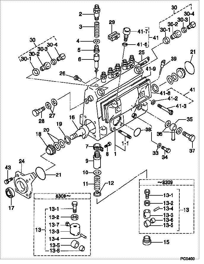
| 000. | [01] | 09010-02600 | BODY ASSY, INJECTI | |
| 001. | [01] | 09010-90031 | HOUSING SUB-ASSY, | 22101-1480 |
| 001. | [01] | 19011-01790 | HOUSING KIT, INJEC | |
| 001-001. | [03] | 94904-30010 | BOLT, STUD | 22857-1060A |
| 002. | [06] | 09013-10020 | HOLDER, DELIVERY V | 6 053 1250 60 |
| 003. | [06] | 09013-60070 | SPRING, DELIVERY V | 6 056 1200 30 |
| 004. | [06] | 09013-70010 | GASKET, DELIVERY V | 22847-1450 |
| 005. | [06] | 09014-00010 | VALVE SUB-ASSY, IN | 2210E-77020 |
| 006. | [06] | 09015-00800 | ELEMENT SUB-ASSY, | 22104-1530 |
| 007. | [06] | 09015-60010 | PINION, PLUNGER CO | 22128-1020A |
| 008. | [06] | 09015-70010 | SCREW, PLUNGER CON | 22865-1280A |
| 009. | [06] | 09016-10330 | SLEEVE, PLUNGER CO | 22118-1310A |
| 010. | [06] | 09016-30191 | SEAT, SPRING, UPR | 22119-1190A |
| 011. | [06] | 09016-40010 | SPRING, PUMP PLUNG | 6 056 1200 80 |
| 012. | [06] | 09016-50010 | SEAT, SPRING, LWR | 22122-1060 |
| 013. | [06] | 09017-00020 | TAPPET SUB-ASSY,IN | 2210G-77020 |
| 013. | [06] | 09017-00130 | TAPPET SUB-ASSY,IN | 22105-1260 |
| 013-001. | [06] | 09017-30010 | BOLT, INJECTION PU | 0901H-30010 |
| 013-002. | [06] | 09017-40010 | NUT, INJECTION PUM | 6 053 1252 40 |
| 013-003. | [06] | 09016-90110 | BODY, INJECTION PU | 6 306 1205 20 |
| 013-003. | [06] | 09016-90130 | BODY, INJECTION PU | 22145-1010 |
| 013-003. | [06] | 09017-10173 | TAPPET, INJECTION | |
| 013-004. | [06] | 09017-60010 | PIN, INJECTION PUM | 22105-1130 |
| 013-005. | [06] | 09018-10010 | ROLLER, INJECTION | 22105-1140 |
| 013-005. | [06] | 09018-10030 | ROLLER, INJECTION | |
| 013-006. | [06] | 09017-80010 | BUSHING, INJECTION | 22105-1150 |
| 013-006. | [06] | 09017-80030 | BUSHING, INJECTION | |
| 013-007. | [06] | 09017-50040 | SLIDER | 6 306 1205 40 |
| 015. | [06] | 09018-90090 | PLUG, INJECTION PU | 22845-1420A |
| 016. | [01] | 09019-10021 | CAMSHAFT, INJECTIO | 22123-1210 |
| 017. | [01] | 94915-01750 | SEAL, OIL | 22823-1220 |
| 018. | [02] | 94910-10120 | BEARING, ROLLER | 22837-1230A |
| 019. | [02] | 09019-30020 | RING, CAMSHAFT ADJ | 22124-1160A |
| 020. | [6C] | 09019-40150 | PLATE, CAMSHAFT SH | 22129-1200A |
| 020. | [6C] | 09019-40140 | PLATE, CAMSHAFT SH | 22129-1190A |
| 020. | [6C] | 09019-40060 | PLATE, CAMSHAFT SH | 22885-4950A |
| 020. | [6C] | 09019-40050 | PLATE, CAMSHAFT SH | 22885-4940A |
| 020. | [6C] | 09019-40040 | PLATE, CAMSHAFT SH | 22885-4930A |
| 020. | [6C] | 09019-40030 | PLATE, CAMSHAFT SH | 22885-4920A |
| 020. | [6C] | 09019-40020 | PLATE, CAMSHAFT SH | 22885-4910A |
| 020. | [6C] | 09019-40010 | PLATE, CAMSHAFT SH | 22885-4900A |
| 021. | [02] | 94914-00060 | O-RING | 22813-1280 |
| 024. | [01] | 09020-10053 | COVER, BEARING | 6 053 1257 10 |
| 025. | [01] | 09021-20010 | RACK, CONTROL | 22113-1320A |
| 026. | [01] | 09021-50060 | SCREW, RACK GUIDE | 22811-4850A |
| 027. | [02] | 94901-02490 | WASHER | 22877-1100A |
| 028. | [01] | 94918-00310 | SCREW, HOLLOW | S2283-51310-A |
| 029. | [03] | 09023-00031 | PLATE SET, VALVE H | 22109-1090A |
| 030. | [02] | 09024-00010 | BLEEDER SUB-ASSY, | 22106-1060 |
| 030-001. | [02] | 09024-10010 | WASHER, AIR BLEEDE | 22847-2150A |
| 030-002. | [02] | 09024-20010 | NIPPLE, AIR BLEEDE | 22873-1250 |
| 030-003. | [02] | 09024-30030 | PACKING, AIR BLEED | 22847-1890A |
| 030-004. | [02] | 09024-40010 | SCREW, AIR BLEEDER | 2211H-77020 |
| 033. | [01] | 09024-80010 | WASHER, DRAIN SCRE | 22847-1730A |
| 034. | [01] | 09024-90010 | SCREW, DRAIN | 6 053 1266 20 |
| 035. | [01] | 09025-00020 | NIPPLE SUB-ASSY, O | 6 056 1325 60 |
| 036. | [02] | 94901-02470 | WASHER | 22847-1900A |
| 037. | [01] | 94918-00060 | SCREW, HOLLOW | 22835-1110A |
| 037. | [01] | 94918-00600 | SCREW, HOLLOW | 22835-1100 |
| 038. | [01] | 94914-00380 | O-RING | 22817-1540A |
| 039. | [01] | 09029-00330 | GAUGE SUB-ASSY, IN | 22112-1110 |
| 041. | [01] | 09027-00700 | COVER SUB-ASSY, IN | 22127-1130 |
| 041-002. | [02] | 09024-30030 | PACKING, AIR BLEED | 22847-1890A |
| 041-003. | [02] | 09027-60030 | SCREW | 22815-1550A |
| 041-006. | [01] | 09024-10010 | WASHER, AIR BLEEDE | 22847-2150A |
| 041-007. | [01] | 09028-00040 | CLEANER, INJECTION | 0 902 8000 40 |
| 041-008. | [01] | 09027-10201 | PLATE, INJECTION P | |
| 041-009. | [01] | 09027-20220 | GASKET, INJECTION | 22847-2180A |
| 043. | [04] | 94904-71360 | BOLT, W/WASHER | 22815-2500A |
Include in #3:
09000-08071
as BODY ASSY, INJECTI
09010-02600
Cross reference number
| Part num | Firm num | Firm | Name |
| 09010-02600 | BODY ASSY, INJECTI |
Information:
Altitude Operation
The fuel system settings and altitude limits are stamped on the engine information plate. When an engine is moved to a higher altitude, these settings must be changed by your Caterpillar dealer in order to prevent damaging the turbocharger, and to provide maximum engine efficiency. If the engine is moved to a lower altitude than that which is stamped on the engine information plate, the engine can be operated safely; however, it will deliver less than rated horsepower, and the fuel settings should be changed by your Caterpillar dealer to obtain rated horsepower.Stopping
1. Flywheel clutch operation: Quickly pull the clutch lever to the released position. For electric set operation, see the GENERATOR SET OPERATION instructions. For Woodward Governor operation, see the topic, WOODWARD GOVERNORS, Stopping the Engine. 2. Reduce engine speed to half speed. Run for 5 minutes to cool engine.3. Reduce engine speed to low idle.4. Observe the crankcase oil level while the engine is idling. Maintain the oil level between the ADD and FULL marks on the side of the dipstick stamped, CHECK WITH ENGINE RUNNING. See the LUBRICATION AND MAINTENANCE SECTION.5. Stop the engine. After Stopping Checks And Procedures
1. Fill the fuel tank. See the LUBRICATION AND MAINTENANCE SECTION: Fuel Tank Maintenance.2. Drain the raw water system if below freezing temperatures are expected; see: Draining Raw Water System.3. If below freezing temperatures are expected, allow the engine jacket water expansion tank to cool; then check the coolant for proper antifreeze protection. Add permanent-type antifreeze, if required.4. Repair any leaks, make major adjustments, tighten loose bolts, etc.5. Observe the Service Meter reading. Perform the periodic maintenance as instructed in the LUBRICATION AND MAINTENANCE CHART.
SERVICE METER