Information body assy, injecti
Rating:
Scheme ###:
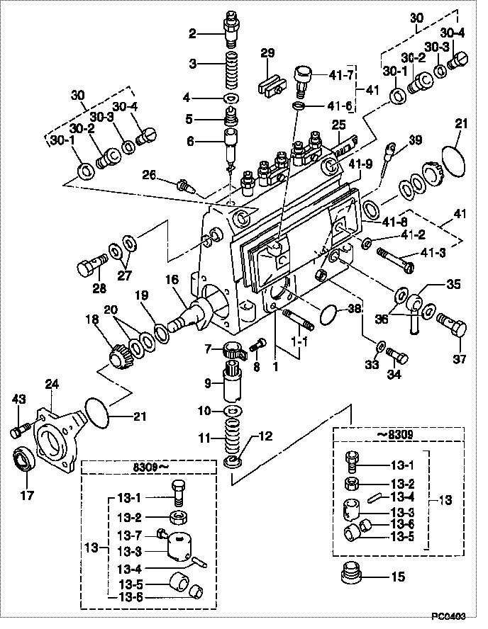
| 000. | [01] | 09010-02291 | BODY ASSY, INJECTI | 22110-1470 |
| 001. | [01] | 19011-01780 | HOUSING KIT, INJEC | 22101-1200 |
| 001-001. | [03] | 94904-30010 | BOLT, STUD | 22857-1060A |
| 002. | [06] | 09013-10020 | HOLDER, DELIVERY V | 6 053 1250 60 |
| 003. | [06] | 09013-60070 | SPRING, DELIVERY V | 6 056 1200 30 |
| 004. | [06] | 09013-70010 | GASKET, DELIVERY V | 22847-1450 |
| 005. | [06] | 09014-00510 | VALVE SUB-ASSY, IN | 22103-1290 |
| 006. | [06] | 09015-01220 | ELEMENT SUB-ASSY, | 22104-1520 |
| 007. | [06] | 09015-60010 | PINION, PLUNGER CO | 22128-1020A |
| 008. | [06] | 09015-70010 | SCREW, PLUNGER CON | 22865-1280A |
| 009. | [06] | 09016-10330 | SLEEVE, PLUNGER CO | 22118-1310A |
| 010. | [06] | 09016-30191 | SEAT, SPRING, UPR | 22119-1190A |
| 011. | [06] | 09016-40010 | SPRING, PUMP PLUNG | 6 056 1200 80 |
| 012. | [06] | 09016-50010 | SEAT, SPRING, LWR | 22122-1060 |
| 013. | [06] | 09017-00020 | TAPPET SUB-ASSY,IN | 2210G-77020 |
| 013. | [06] | 09017-00130 | TAPPET SUB-ASSY,IN | 22105-1260 |
| 013-001. | [06] | 09017-30010 | BOLT, INJECTION PU | 0901H-30010 |
| 013-002. | [06] | 09017-40010 | NUT, INJECTION PUM | 6 053 1252 40 |
| 013-003. | [06] | 09017-10173 | TAPPET, INJECTION | |
| 013-003. | [06] | 09016-90130 | BODY, INJECTION PU | 22145-1010 |
| 013-003. | [06] | 09016-90110 | BODY, INJECTION PU | 6 306 1205 20 |
| 013-004. | [06] | 09017-60010 | PIN, INJECTION PUM | 22105-1130 |
| 013-005. | [06] | 09018-10010 | ROLLER, INJECTION | 22105-1140 |
| 013-005. | [06] | 09018-10030 | ROLLER, INJECTION | |
| 013-006. | [06] | 09017-80010 | BUSHING, INJECTION | 22105-1150 |
| 013-006. | [06] | 09017-80030 | BUSHING, INJECTION | |
| 013-007. | [06] | 09017-50040 | SLIDER | 6 306 1205 40 |
| 015. | [06] | 09018-90090 | PLUG, INJECTION PU | 22845-1420A |
| 016. | [01] | 09019-10021 | CAMSHAFT, INJECTIO | 22123-1210 |
| 017. | [01] | 94915-01750 | SEAL, OIL | 22823-1220 |
| 018. | [02] | 94910-10120 | BEARING, ROLLER | 22837-1230A |
| 019. | [02] | 09019-30020 | RING, CAMSHAFT ADJ | 22124-1160A |
| 020. | [6C] | 09019-40150 | PLATE, CAMSHAFT SH | 22129-1200A |
| 020. | [6C] | 09019-40140 | PLATE, CAMSHAFT SH | 22129-1190A |
| 020. | [6C] | 09019-40060 | PLATE, CAMSHAFT SH | 22885-4950A |
| 020. | [6C] | 09019-40050 | PLATE, CAMSHAFT SH | 22885-4940A |
| 020. | [6C] | 09019-40040 | PLATE, CAMSHAFT SH | 22885-4930A |
| 020. | [6C] | 09019-40030 | PLATE, CAMSHAFT SH | 22885-4920A |
| 020. | [6C] | 09019-40020 | PLATE, CAMSHAFT SH | 22885-4910A |
| 020. | [6C] | 09019-40010 | PLATE, CAMSHAFT SH | 22885-4900A |
| 021. | [02] | 94914-00060 | O-RING | 22813-1280 |
| 024. | [01] | 09020-10053 | COVER, BEARING | 6 053 1257 10 |
| 025. | [01] | 09021-20010 | RACK, CONTROL | 22113-1320A |
| 026. | [01] | 09021-50060 | SCREW, RACK GUIDE | 22811-4850A |
| 027. | [02] | 94901-02490 | WASHER | 22877-1100A |
| 028. | [01] | 94918-00310 | SCREW, HOLLOW | 22835-1310A |
| 029. | [03] | 09023-00031 | PLATE SET, VALVE H | 22109-1090A |
| 030. | [02] | 09024-00010 | BLEEDER SUB-ASSY, | 22106-1060 |
| 030-001. | [02] | 09024-10010 | WASHER, AIR BLEEDE | 22847-2150A |
| 030-002. | [02] | 09024-20010 | NIPPLE, AIR BLEEDE | 22873-1250 |
| 030-003. | [02] | 09024-30030 | PACKING, AIR BLEED | 22847-1890A |
| 030-004. | [02] | 09024-40010 | SCREW, AIR BLEEDER | 2211H-77020 |
| 033. | [01] | 09024-80010 | WASHER, DRAIN SCRE | 22847-1730A |
| 034. | [01] | 09024-90010 | SCREW, DRAIN | 6 053 1266 20 |
| 035. | [01] | 09025-00020 | NIPPLE SUB-ASSY, O | 6 056 1325 60 |
| 036. | [02] | 94901-02470 | WASHER | 22847-1900A |
| 037. | [01] | 94918-00060 | SCREW, HOLLOW | 22835-1110A |
| 037. | [01] | 94918-00600 | SCREW, HOLLOW | 22835-1100 |
| 038. | [01] | 94914-00380 | O-RING | 22817-1540A |
| 039. | [01] | 09029-00330 | GAUGE SUB-ASSY, IN | 22112-1110 |
| 041. | [01] | 09027-00840 | COVER SUB-ASSY, IN | 22102-1130 |
| 041-002. | [02] | 09024-30030 | PACKING, AIR BLEED | 22847-1890A |
| 041-003. | [02] | 09027-60030 | SCREW | 22815-1550A |
| 041-006. | [01] | 09024-10010 | WASHER, AIR BLEEDE | 22847-2150A |
| 041-007. | [01] | 09028-00040 | CLEANER, INJECTION | 0 902 8000 40 |
| 041-008. | [01] | 09027-10201 | PLATE, INJECTION P | |
| 041-009. | [01] | 09027-20220 | GASKET, INJECTION | 22847-2180A |
| 043. | [04] | 94904-71360 | BOLT, W/WASHER | 22815-2500A |
Include in #3:
09000-07144
as BODY ASSY, INJECTI
09010-02291
Cross reference number
| Part num | Firm num | Firm | Name |
| 09010-02291 | 22110-1470 | BODY ASSY, INJECTI |
Information:
This Program must be administered as soon as possible. When reporting the repair, use "PI3330" as the Part Number, "7751" as the Group Number, "56" as the Warranty Claim Description Code and "T" as the SIMS Description Code. Exception: If the repair is done after failure, use "PI3330" as the Part Number, "7751" as the Group Number, "96" as the Warranty Claim Description Code, and "Z" as the SIMS Description Code.
Completion Date
March 31, 2000Termination Date
September 30, 2000Problem
The torque of the injector electronic solenoid valves need to be checked. The valve has four Torx bolts that hold the stator to the housing. If these bolts are not properly tightened, fuel can leak into the oil.
Affected Product
Model & Identification Number
D11R (9TR441-442)
776D (5ER126, 5ER127)
785C (1HW122)
793C (4GZ165-167)
777D (3PR1058, 3PR1057, 3PR1061, 3PR1059, 3PR1060, 3PR1063)
3508B (3DM157-159 4GM426-439 6PN532-533 , 6PN535-536, 6PN539-540, 6PN542-543 5PS225-234 2HW125-126 1FZ366-370 )
3512 (6PM38-39 3MS186 3RS329 )
3512B (8EM317-318 8RM395-397 4TM215-217 3ZW131-134 6WN349-356 )
3516 (7KM50-51 3SS306-307 )
3516B (6HN384, 6HN390, 6HN392, 6HN394, 6HN398 7RN818-819 , 7RN821, 7RN824, 7RN826-827, 7RN833, 7RN836-840, 7RN850, 7RN852 8KN368-369 , 8KN372, 8KN373 7TR818 4BW333-334 )
Parts Needed
Dealers will not need to order parts for this Program.
Action Required
See the attached procedure.
Owner Notification
U.S. and Canadian owners will receive the attached Owner Notification.
Service Claim Allowances
This is a 3-hour job.
U.S. and Canadian Dealers Only - Eligible dealers may enter a Type 2 SIMS Report.
Parts Disposition
Handle the parts in accordance with your Warranty Bulletin on warranty parts handling.
MAKE EVERY EFFORT TO COMPLETE THIS PROGRAM AS SOON AS POSSIBLE.
Attach.(1-Owner Notification)(Torque Procedure)Copy Of Owner Notification For U.S. And Canadian Owners
Torque Procedure For Electronic 3500B Injector Bolts
THIS REWORK IS RESTRICTED TO ENGINES LISTED IN THE AFFECTED PRODUCT ONLY.
THIS PIP DOES NOT ALLOW FOR THE REMOVAL OF THE INJECTOR. DO NOT REMOVE ANY OF THE STATOR BOLTS. THIS WILL VOID INJECTOR WARRANTY.
PROCEDURE:
1. Remove the valve covers to reveal the injector assembly/ electronic valve.2. Remove electronic valve terminal connector (two retaining nuts) with a " universal socket. Take the terminal connectors off of the posts.3. The four stator retaining bolts you need to check are now accessible. To properly complete the torque check, the following tools are required.a) Click torque wrench, " drive (capable of accurately measuring 2.0 N m)b) 6" extension " drive.c) universal joint, "drived) T10 Torx bit, " drive4. Set the torque wrench value to (2.1 N m). Check all four bolts and tighten (if needed) until they reach the 2.1 specification.:
DO NOT OVER TORQUE THE STATOR RETAINING BOLTS (2.1 N m). THIS COULD CAUSE FURTHER DAMAGE.
5. Reassemble the engine in the reverse order.a) Torque value of the terminal connector nuts - 3.0 N m b) Torque value for the valve cover bolts - 47 9 N m.