Information body assy, injecti
Rating:
Scheme ###:
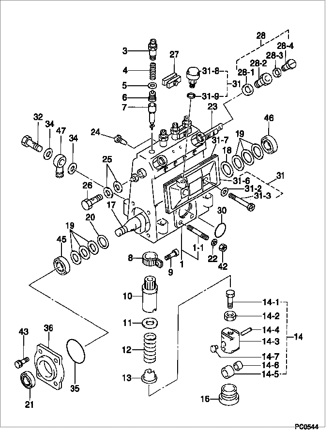
| 000. | [01] | 09010-02190 | BODY ASSY, INJECTI | 09010-02190 |
| 001. | [01] | 09010-91170 | HOUSING SUB-ASSY, | 09010-91170 |
| 001-001. | [03] | 94904-30010 | BOLT, STUD | 94904-30010 |
| 003. | [04] | 09013-10020 | HOLDER, DELIVERY V | 09013-10020 |
| 004. | [04] | 09013-60010 | SPRING, DELIVERY V | 09013-60010 |
| 005. | [04] | 09013-70010 | GASKET, DELIVERY V | 09013-70010 |
| 006. | [04] | 09014-00021 | VALVE SUB-ASSY, IN | 09014-00021 |
| 007. | [04] | 09015-00390 | ELEMENT SUB-ASSY, | 09015-00390 |
| 008. | [04] | 09015-60010 | PINION, PLUNGER CO | 09015-60010 |
| 009. | [04] | 09015-70010 | SCREW, PLUNGER CON | 09015-70010 |
| 010. | [04] | 09016-10330 | SLEEVE, PLUNGER CO | |
| 011. | [04] | 09016-30120 | SEAT, SPRING, UPR | |
| 011. | [04] | 09016-30191 | SEAT, SPRING, UPR | |
| 012. | [04] | 09016-40020 | SPRING, PUMP PLUNG | 09016-40020 |
| 013. | [04] | 09016-50010 | SEAT, SPRING, LWR | 09016-50010 |
| 014. | [04] | 09017-00020 | TAPPET SUB-ASSY,IN | 09017-00020 |
| 014. | [04] | 09017-00130 | TAPPET SUB-ASSY,IN | 09017-00130 |
| 014-001. | [04] | 09017-30010 | BOLT, INJECTION PU | 09017-30010 |
| 014-002. | [04] | 09017-40010 | NUT, INJECTION PUM | 09017-40010 |
| 014-003. | [04] | 09016-90110 | BODY, INJECTION PU | 09016-90110 |
| 014-003. | [04] | 09016-90130 | BODY, INJECTION PU | 09016-90130 |
| 014-003. | [04] | 09017-10173 | TAPPET, INJECTION | 09017-10171 |
| 014-004. | [04] | 09017-60010 | PIN, INJECTION PUM | 09017-60010 |
| 014-005. | [04] | 09018-10010 | ROLLER, INJECTION | 09018-10010 |
| 014-005. | [04] | 09018-10030 | ROLLER, INJECTION | 09018-10030 |
| 014-006. | [04] | 09017-80010 | BUSHING, INJECTION | 09017-80010 |
| 014-006. | [04] | 09017-80030 | BUSHING, INJECTION | 09017-80030 |
| 014-007. | [04] | 09017-50040 | SLIDER | |
| 016. | [04] | 09018-90090 | PLUG, INJECTION PU | |
| 017. | [01] | 09019-10082 | CAMSHAFT, INJECTIO | 09019-10081 |
| 018. | [01] | 09019-30041 | RING, CAMSHAFT ADJ | 09019-30041 |
| 019. | [6C] | 09019-40400 | PLATE, CAMSHAFT SH | |
| 019. | [6C] | 09019-40290 | PLATE, CAMSHAFT SH | |
| 019. | [6C] | 09019-40150 | PLATE, CAMSHAFT SH | 09019-40150 |
| 019. | [6C] | 09019-40140 | PLATE, CAMSHAFT SH | 09019-40140 |
| 019. | [6C] | 09019-40110 | PLATE, CAMSHAFT SH | 09019-40110 |
| 019. | [6C] | 09019-40060 | PLATE, CAMSHAFT SH | 09019-40060 |
| 019. | [6C] | 09019-40050 | PLATE, CAMSHAFT SH | 09019-40050 |
| 019. | [6C] | 09019-40040 | PLATE, CAMSHAFT SH | 09019-40040 |
| 019. | [6C] | 09019-40030 | PLATE, CAMSHAFT SH | 09019-40030 |
| 019. | [6C] | 09019-40020 | PLATE, CAMSHAFT SH | 09019-40020 |
| 019. | [6C] | 09019-40010 | PLATE, CAMSHAFT SH | 09019-40010 |
| 020. | [01] | 09019-30030 | RING, CAMSHAFT ADJ | 09019-30030 |
| 021. | [01] | 94915-01760 | SEAL, OIL | |
| 022. | [03] | 90258-06001 | WASHER, SPRING | 90258-06001 |
| 023. | [01] | 09021-20020 | RACK, CONTROL | 09021-20020 |
| 024. | [01] | 09021-50060 | SCREW, RACK GUIDE | |
| 025. | [02] | 09022-20050 | WASHER, FUEL PIPE | 09022-20050 |
| 026. | [01] | 94918-00310 | SCREW, HOLLOW | 94918-00310 |
| 027. | [02] | 09023-00031 | PLATE SET, VALVE H | 09023-00031 |
| 028. | [01] | 09024-00040 | BLEEDER SUB-ASSY, | |
| 028-001. | [01] | 09024-10010 | WASHER, AIR BLEEDE | 09024-10010 |
| 028-002. | [01] | 09024-20010 | NIPPLE, AIR BLEEDE | 09024-20010 |
| 028-003. | [01] | 09024-80010 | WASHER, DRAIN SCRE | 09024-80010 |
| 028-004. | [01] | 09024-40010 | SCREW, AIR BLEEDER | 09024-40010 |
| 030. | [01] | 94914-01380 | O-RING | |
| 031. | [01] | 09027-00810 | COVER SUB-ASSY, IN | 09027-00810 |
| 031-002. | [02] | 94901-03020 | WASHER | |
| 031-003. | [02] | 09027-60030 | SCREW | 09027-60030 |
| 031-006. | [01] | 09027-10211 | PLATE, INJECTION P | |
| 031-007. | [01] | 09027-20240 | GASKET, INJECTION | |
| 031-008. | [01] | 09028-00040 | CLEANER, INJECTION | 09028-00040 |
| 031-009. | [01] | 09024-10010 | WASHER, AIR BLEEDE | 09024-10010 |
| 032. | [01] | 94918-00060 | SCREW, HOLLOW | 94918-00060 |
| 034. | [02] | 09025-10010 | WASHER, INJECTION | 09025-10010 |
| 035. | [01] | 94914-01390 | O-RING | |
| 036. | [01] | 09020-10081 | COVER, BEARING | 09020-10081 |
| 042. | [03] | 90160-06051 | NUT, HEXAGON | 90160-06051 |
| 043. | [04] | 94904-71360 | BOLT, W/WASHER | 94904-71360 |
| 045. | [01] | 94910-00080 | BEARING, BALL | 94910-00080 |
| 046. | [01] | 94910-00660 | BEARING, BALL | 94910-00660 |
| 047. | [01] | 09025-00030 | NIPPLE SUB-ASSY, O | 09025-00030 |
Include in #3:
09000-07261
as BODY ASSY, INJECTI
09010-02190
Cross reference number
| Part num | Firm num | Firm | Name |
| 09010-02190 | BODY ASSY, INJECTI | ||
| 09010-02190 | KOMATSU | BODY ASSY, INJECTI |
Information:
* NA: Naturally Aspirated* T: Turbocharged* TA: Turbocharged, Aftercooled* DI: Direct Injection* PC: Precombustion ChamberThis instruction gives the information needed to install a service replacement fuel injection pump and governor group for the above engines.1 Remove the fuel system from the engine. Make reference to the Service Manual for correct procedure.
When any replacement parts are put in the fuel system, the low idle, high idle and fuel setting must be checked and adjustments made as necessary. Only a mechanic with training in fuel system maintenance must be permitted to make these adjustments. The correct low idle and high idle rpm, and fuel setting are given in the FUEL SETTING INFORMATION.
2 Find and write down the serial number of the machine, the serial number of the engine and the engine arrangement number. All of these numbers are needed to find which parts to use for the fuel system reconditioning. 3 The chart that follows gives the part number of the governor spring (1) that is already installed in each Service Pump Group. Make reference to the FUEL SETTING INFORMATION, to find the part number of the governor spring needed for the fuel system reconditioning. If the governor spring must be changed, the chart for governor spring identification gives a method to find the correct governor spring. See the Service Manual for the procedure needed to change the governor spring. 4 The chart that follows gives the part number of the detent spring that is installed in the governor control of each service group. Look at the Parts Book for the specific engine or machine, to find which detent spring is needed for the fuel system reconditioning. If it is necessary to change detent spring (2), see the Service Manual for the procedure to install the detent spring. The illustrations with steps 4 and 5 show a 4 cylinder engine fuel system only; the procedure is the same for a 6 cylinder engine fuel system. 5 Make a comparison of side cover (3) on the new pump housing in the service group and the side cover on the old pump housing. If the side covers are different, they must be exchanged. The new pump housing must have the same type of side cover that is installed on the old pump housing. Use new gaskets when the side cover is exchanged. 6 Remove cover (4) from the new service group and the similar cover from the old fuel system. If the torque control groups are different, they must be exchanged. The torque control group on the new pump housing must be the same as the torque control group on the old pump housing. 7 The new service group has one bolt (5) and a stud (6) with nut (7) to fasten the torque control group in position. For those earlier fuel systems that had two bolts, similar to bolt (5), and did not have stud (6) and nut (7), use only the one bolt (5) and stud (6) with nut