Information body assy, injecti
Rating:
Scheme ###:
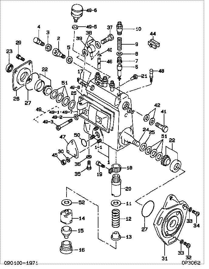
| 000. | [01] | 09010-01971 | BODY ASSY, INJECTI | |
| 001. | [01] | 09010-90373 | HOUSING SUB-ASSY, | |
| 001-001. | [03] | 94904-30010 | BOLT, STUD | |
| 002. | [01] | 09024-20010 | NIPPLE, AIR BLEEDE | |
| 003. | [01] | 09024-30030 | PACKING, AIR BLEED | |
| 004. | [01] | 09024-40010 | SCREW, AIR BLEEDER | 22117-77020 |
| 005. | [01] | 09024-10010 | WASHER, AIR BLEEDE | 22191-73600-71 |
| 006. | [04] | 09015-01200 | ELEMENT SUB-ASSY, | |
| 006. | [04] | 09015-01270 | ELEMENT SUB-ASSY, | |
| 007. | [04] | 09014-00010 | VALVE SUB-ASSY, IN | 22104-77020 |
| 008. | [04] | 09013-70010 | GASKET, DELIVERY V | |
| 009. | [04] | 09013-60050 | SPRING, DELIVERY V | |
| 010. | [04] | 09013-10010 | HOLDER, DELIVERY V | |
| 011. | [04] | 09016-30010 | SEAT, SPRING, UPR | |
| 011. | [04] | 09016-30191 | SEAT, SPRING, UPR | |
| 012. | [04] | 09016-40090 | SPRING, PUMP PLUNG | |
| 013. | [04] | 09016-50020 | SEAT, SPRING, LWR | |
| 014. | [04] | 09017-00070 | TAPPET SUB-ASSY,IN | |
| 015. | [04] | 09018-80010 | PLATE, INJECTION P | |
| 016. | [04] | 09018-90060 | PLUG, INJECTION PU | |
| 016. | [04] | 09018-90090 | PLUG, INJECTION PU | |
| 017. | [01] | 09021-20110 | RACK, CONTROL | |
| 018. | [04] | 09015-60010 | PINION, PLUNGER CO | |
| 019. | [04] | 09015-70010 | SCREW, PLUNGER CON | |
| 020. | [04] | 09016-10330 | SLEEVE, PLUNGER CO | |
| 021. | [01] | 09021-50060 | SCREW, RACK GUIDE | |
| 022. | [02] | 94910-10120 | BEARING, ROLLER | |
| 023. | [01] | 94915-00050 | SEAL, OIL | 22537-30890-71 |
| 023. | [01] | 94915-01750 | SEAL, OIL | |
| 024. | [01] | 09019-10082 | CAMSHAFT, INJECTIO | |
| 025. | [02] | 09019-30020 | RING, CAMSHAFT ADJ | |
| 027. | [01] | 94914-00060 | O-RING | |
| 028. | [01] | 09020-10090 | COVER, BEARING | |
| 029. | [04] | 94904-10131 | BOLT, SLOTTED HEXA | |
| 030. | [03] | 90258-06001 | WASHER, SPRING | 94511-00600 |
| 031. | [01] | 09020-40111 | FLANGE, INJECTION | |
| 032. | [04] | 94900-72471 | SCREW, W/WASHER | |
| 032. | [04] | 90000-08201 | SCREW, SLOTTED PAN | |
| 033. | [05] | 90258-08001 | WASHER, SPRING | 94511-00800 |
| 033. | [01] | 90258-08001 | WASHER, SPRING | 94511-00800 |
| 034. | [01] | 94900-62961 | SCREW | |
| 035. | [01] | 09024-90010 | SCREW, DRAIN | |
| 036. | [01] | 09024-80010 | WASHER, DRAIN SCRE | 22121-30890-71 |
| 037. | [01] | 94918-00091 | SCREW, HOLLOW | |
| 037. | [01] | 94918-00600 | SCREW, HOLLOW | |
| 038. | [02] | 09025-10010 | WASHER, INJECTION | |
| 039. | [01] | 19025-00080 | PIPE ASSY, OVERFLO | |
| 039. | [01] | 09025-00030 | NIPPLE SUB-ASSY, O | |
| 039. | [01] | 09025-00170 | NIPPLE SUB-ASSY, O | |
| 039. | [01] | 09025-00030 | NIPPLE SUB-ASSY, O | |
| 040. | [01] | 94919-20520 | COLLAR, STEEL | |
| 040. | [01] | 94935-10010 | CLIP, HOSE | |
| 041. | [01] | 94918-00310 | SCREW, HOLLOW | 90099-18010 |
| 042. | [02] | 09022-20070 | WASHER, FUEL PIPE | 94712-77121 |
| 042. | [02] | 09022-20031 | WASHER, FUEL PIPE | |
| 044. | [02] | 09023-00031 | PLATE SET, VALVE H | |
| 045. | [03] | 90160-06051 | NUT, HEXAGON | 94110-40600 |
| 046. | [01] | 09025-70050 | PIPE, OVER FLOW | |
| 047. | [01] | 09010-40010 | PLATE, COVER | |
| 048. | [01] | 09029-00321 | GAUGE SUB-ASSY, IN | |
| 048. | [01] | 09029-00182 | GAUGE SUB-ASSY, IN | |
| 049. | [01] | 09027-00630 | COVER SUB-ASSY, IN | 25705-30170-71 |
| 049-001. | [01] | 09026-90050 | PLATE, INJECTION P | |
| 049-002. | [02] | 09024-30030 | PACKING, AIR BLEED | |
| 049-003. | [02] | 09027-60030 | SCREW | |
| 049-003. | [02] | 09027-60020 | SCREW | |
| 049-005. | [01] | 09024-10010 | WASHER, AIR BLEEDE | 22191-73600-71 |
| 049-006. | [01] | 09028-00040 | CLEANER, INJECTION | 22151-46021 |
| 049-006. | [01] | 09028-00060 | CLEANER, INJECTION | |
| 049-007. | [01] | 09027-10211 | PLATE, INJECTION P | |
| 049-008. | [01] | 09027-20210 | GASKET, INJECTION | |
| 050. | [01] | 94914-00380 | O-RING | |
| 051. | [6C] | 09019-40010 | PLATE, CAMSHAFT SH | |
| 051. | [6C] | 09019-40150 | PLATE, CAMSHAFT SH | |
| 051. | [6C] | 09019-40140 | PLATE, CAMSHAFT SH | |
| 051. | [6C] | 09019-40060 | PLATE, CAMSHAFT SH | |
| 051. | [6C] | 09019-40050 | PLATE, CAMSHAFT SH | |
| 051. | [6C] | 09019-40040 | PLATE, CAMSHAFT SH | |
| 051. | [6C] | 09019-40030 | PLATE, CAMSHAFT SH | |
| 051. | [6C] | 09019-40020 | PLATE, CAMSHAFT SH | |
| 052. | [4C] | 09031-10090 | PLATE, TAPPET ADJU | |
| 052. | [4C] | 09031-10100 | PLATE, TAPPET ADJU | |
| 052. | [4C] | 09031-10110 | PLATE, TAPPET ADJU | |
| 052. | [4C] | 09031-10120 | PLATE, TAPPET ADJU | |
| 052. | [4C] | 09031-10130 | PLATE, TAPPET ADJU | |
| 052. | [4C] | 09031-10140 | PLATE, TAPPET ADJU | |
| 052. | [4C] | 09031-10080 | PLATE, TAPPET ADJU | |
| 052. | [4C] | 09031-10070 | PLATE, TAPPET ADJU | |
| 052. | [4C] | 09031-10060 | PLATE, TAPPET ADJU | |
| 052. | [4C] | 09031-10050 | PLATE, TAPPET ADJU | |
| 052. | [4C] | 09031-10040 | PLATE, TAPPET ADJU | |
| 052. | [4C] | 09031-10030 | PLATE, TAPPET ADJU | |
| 052. | [4C] | 09031-10020 | PLATE, TAPPET ADJU | |
| 052. | [4C] | 09031-10010 | PLATE, TAPPET ADJU | |
| 052. | [4C] | 09031-10150 | PLATE, TAPPET ADJU |
Include in #3:
09000-06460
as BODY ASSY, INJECTI
09010-01971
Cross reference number
| Part num | Firm num | Firm | Name |
| 09010-01971 | BODY ASSY, INJECTI |
Information:
1. Disconnect fuel line (3) from the fuel transfer pump. Cap or plug immediately.2. Disconnect fuel line (4) from the fuel transfer pump. Cap or plug immediately.3. Remove bolts (1).4. Remove fuel transfer pump (2). Check the condition of the O-ring seal on the fuel transfer pump. If necessary, make a replacement. Put clean engine oil on the O-ring seal when assembling fuel transfer pump. For installation of the fuel transfer pump, reverse the removal steps.Disassemble & Assemble Fuel Transfer Pump
Start By:a. remove fuel transfer pump 1. Remove seal (1) from the fuel transfer pump.
Cover (2) is under spring tension. Remove the bolts that hold cover (2) slowly to prevent injury.
2. Remove bolts (3) and cover (2) the housing. 3. Remove seals (4) and valve (5) from cover (2). 4. Remove spring (6) from the piston.
Mark the orientation of valve (8) as to its location in the housing.
5. Remove washer (7) and valve (8) from the housing. 6. Remove piston (9) and sleeve (10) from the housing. 7. Remove seal (11) from sleeve (12). 8. Remove guide and tappet assembly (13) from the housing. 9. Remove seal (14) from guide (15).
If tappet (17) or guide (15) are damaged or worn, they must be replaced as a unit.
10. Remove ring (16) from tappet (17) and the tappet from guide (15). 11. Remove the bolts and cover (18) from the housing. 12. Remove seal (19) from cover (18). 13. Remove valve (20) from the housing. The following steps are for the assembly of the fuel transfer pump.14. Install valve (20) in the housing. Put clean fuel on seal (19) and install it on cover (18). Install the cover on the housing.15. Install tappet (17) in guide (15). Install ring (16) on tappet (17) to hold the tappet in the guide.16. Put clean fuel on seal (14) and install it on the guide and tappet assembly (13). Install guide and tappet assembly (13) in the housing.17. Put clean fuel on seal (11) and install it on sleeve (12). Install sleeve (12) in the housing.18. Install piston (9) in the housing. Install valve (8) and washer (7) in the housing. Install spring (6) in the piston.19. Install valve (5) in cover (2).20. Put clean fuel on seals (4) and put them in position on cover (2). Install cover (2) on the housing.21. Put seal (1) in position on the fuel transfer pump.End By:a. install fuel transfer pump