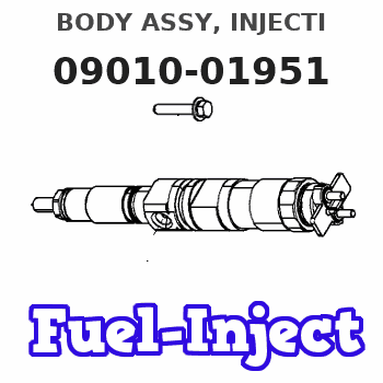
Information body assy, injecti
Rating:
Scheme ###:
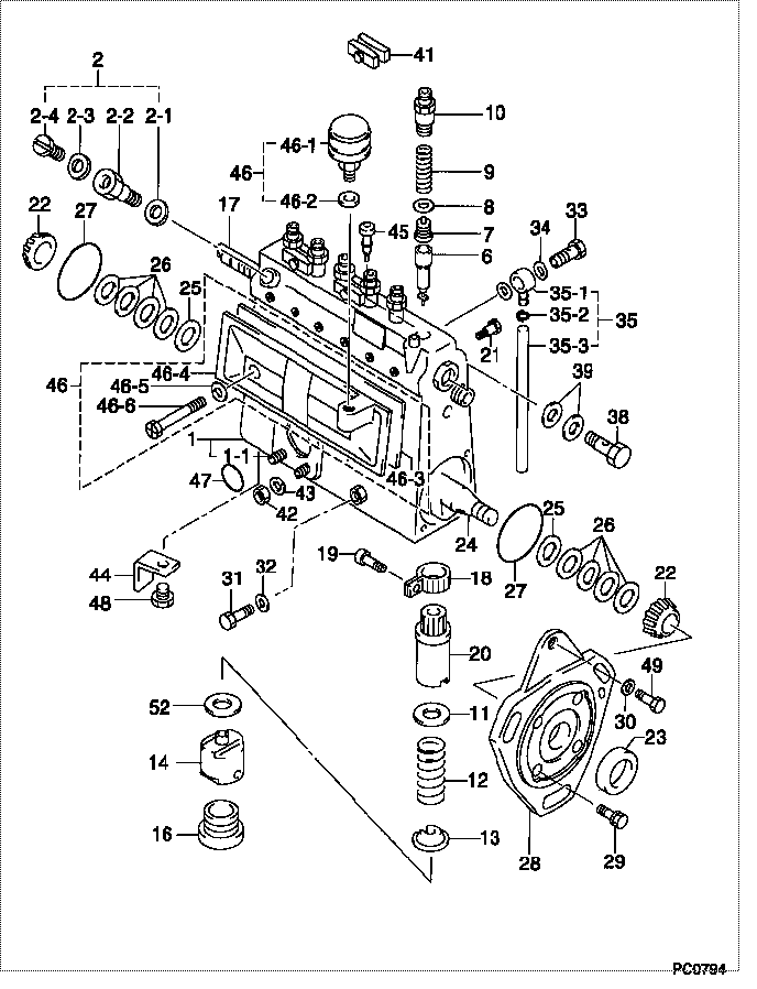
| 000. | [01] | 09010-01951 | BODY ASSY, INJECTI | 22120-47021 |
| 001. | [01] | 09010-90780 | HOUSING SUB-ASSY, | 22101-47012 |
| 001-001. | [03] | 94904-30010 | BOLT, STUD | 90099-04071 |
| 002. | [02] | 09024-00010 | BLEEDER SUB-ASSY, | 22150-67010 |
| 002-001. | [02] | 09024-10010 | WASHER, AIR BLEEDE | 22119-77020 |
| 002-002. | [02] | 09024-20010 | NIPPLE, AIR BLEEDE | 22118-77020 |
| 002-003. | [02] | 09024-30030 | PACKING, AIR BLEED | 22121-77020 |
| 002-004. | [02] | 09024-40010 | SCREW, AIR BLEEDER | 22117-77020 |
| 006. | [06] | 09015-01270 | ELEMENT SUB-ASSY, | 22105-48023 |
| 007. | [06] | 09014-00010 | VALVE SUB-ASSY, IN | 22104-77020 |
| 008. | [06] | 09013-70010 | GASKET, DELIVERY V | 22149-76010 |
| 009. | [06] | 09013-60050 | SPRING, DELIVERY V | 22148-46010 |
| 010. | [06] | 09013-10010 | HOLDER, DELIVERY V | 22131-77020 |
| 011. | [06] | 09016-30191 | SEAT, SPRING, UPR | 22143-78150 |
| 012. | [06] | 09016-40090 | SPRING, PUMP PLUNG | 22144-46010 |
| 013. | [06] | 09016-50020 | SEAT, SPRING, LWR | 22145-46010 |
| 014. | [06] | 09017-00070 | TAPPET SUB-ASSY,IN | 22106-46010 |
| 016. | [06] | 09018-90090 | PLUG, INJECTION PU | 22157-48024 |
| 017. | [01] | 09021-20180 | RACK, CONTROL | 22114-47010 |
| 018. | [06] | 09015-60010 | PINION, PLUNGER CO | 22155-76010 |
| 019. | [06] | 09015-70010 | SCREW, PLUNGER CON | 22156-76010 |
| 020. | [06] | 09016-10330 | SLEEVE, PLUNGER CO | 22142-58230 |
| 021. | [01] | 09021-50060 | SCREW, RACK GUIDE | 22115-78140 |
| 022. | [02] | 94910-10120 | BEARING, ROLLER | 90099-10087 |
| 023. | [01] | 94915-01750 | SEAL, OIL | |
| 024. | [01] | 09019-10710 | CAMSHAFT, INJECTIO | 22146-68010 |
| 025. | [02] | 09019-30020 | RING, CAMSHAFT ADJ | 22147-77020 |
| 026. | [6C] | 09019-40150 | PLATE, CAMSHAFT SH | 22166-78031 |
| 026. | [6C] | 09019-40140 | PLATE, CAMSHAFT SH | 22166-78030 |
| 026. | [6C] | 09019-40060 | PLATE, CAMSHAFT SH | 22166-76010 |
| 026. | [6C] | 09019-40050 | PLATE, CAMSHAFT SH | 22165-76010 |
| 026. | [6C] | 09019-40040 | PLATE, CAMSHAFT SH | 22164-76010 |
| 026. | [6C] | 09019-40030 | PLATE, CAMSHAFT SH | 22163-76010 |
| 026. | [6C] | 09019-40020 | PLATE, CAMSHAFT SH | 22162-76010 |
| 026. | [6C] | 09019-40010 | PLATE, CAMSHAFT SH | 22161-76010 |
| 027. | [02] | 94914-00060 | O-RING | 90099-14002 |
| 028. | [01] | 09020-40111 | FLANGE, INJECTION | 22181-48021 |
| 029. | [04] | 94900-72471 | SCREW, W/WASHER | 90099-00928 |
| 030. | [01] | 90258-08001 | WASHER, SPRING | 94511-00800 |
| 031. | [01] | 09024-90010 | SCREW, DRAIN | 22122-77020 |
| 032. | [01] | 09024-80010 | WASHER, DRAIN SCRE | 22378-76010 |
| 033. | [01] | 94918-00600 | SCREW, HOLLOW | |
| 034. | [02] | 09025-10010 | WASHER, INJECTION | 22124-77020 |
| 035. | [01] | 19025-00040 | PIPE ASSY, OVERFLO | |
| 035-001. | [01] | 09025-00171 | NIPPLE SUB-ASSY, O | |
| 035-002. | [01] | 94907-21030 | RING, SNAP | |
| 035-003. | [01] | 09025-70051 | PIPE, OVER FLOW | 22198-46020 |
| 038. | [01] | 94918-00310 | SCREW, HOLLOW | 90099-18010 |
| 039. | [02] | 09022-20070 | WASHER, FUEL PIPE | 94712-77121 |
| 041. | [02] | 09023-00031 | PLATE SET, VALVE H | 22102-77021 |
| 042. | [03] | 90160-06051 | NUT, HEXAGON | 90092-10101 |
| 043. | [03] | 90258-06001 | WASHER, SPRING | 94511-00600 |
| 044. | [01] | 09045-30011 | STAY, INJECTION PU | 22177-47010 |
| 045. | [01] | 09029-00321 | GAUGE SUB-ASSY, IN | 22112-56011 |
| 046. | [01] | 09027-00880 | COVER SUB-ASSY, IN | |
| 046-001. | [01] | 09028-00060 | CLEANER, INJECTION | 22151-56010 |
| 046-002. | [01] | 09024-10010 | WASHER, AIR BLEEDE | 22119-77020 |
| 046-003. | [01] | 09027-20220 | GASKET, INJECTION | |
| 046-004. | [01] | 09027-10201 | PLATE, INJECTION P | |
| 046-005. | [02] | 09024-30030 | PACKING, AIR BLEED | 22121-77020 |
| 046-006. | [02] | 09027-60030 | SCREW | |
| 047. | [01] | 94914-00380 | O-RING | 90099-14015 |
| 048. | [02] | 91410-08141 | BOLT, W/WASHER | 91611-40814 |
| 049. | [01] | 94900-62961 | SCREW | 90099-00894 |
| 052. | [6C] | 09031-10090 | PLATE, TAPPET ADJU | 22189-48036 |
| 052. | [6C] | 09031-10100 | PLATE, TAPPET ADJU | 22182-46010 |
| 052. | [6C] | 09031-10110 | PLATE, TAPPET ADJU | 22183-46010 |
| 052. | [6C] | 09031-10120 | PLATE, TAPPET ADJU | 22184-46010 |
| 052. | [6C] | 09031-10130 | PLATE, TAPPET ADJU | 22185-46010 |
| 052. | [6C] | 09031-10140 | PLATE, TAPPET ADJU | 22186-46010 |
| 052. | [6C] | 09031-10080 | PLATE, TAPPET ADJU | 22189-48035 |
| 052. | [6C] | 09031-10070 | PLATE, TAPPET ADJU | 22189-48034 |
| 052. | [6C] | 09031-10060 | PLATE, TAPPET ADJU | 22189-48033 |
| 052. | [6C] | 09031-10050 | PLATE, TAPPET ADJU | 22189-48032 |
| 052. | [6C] | 09031-10040 | PLATE, TAPPET ADJU | 22189-48031 |
| 052. | [6C] | 09031-10030 | PLATE, TAPPET ADJU | 22189-46010 |
| 052. | [6C] | 09031-10020 | PLATE, TAPPET ADJU | 22188-46010 |
| 052. | [6C] | 09031-10010 | PLATE, TAPPET ADJU | 22187-46010 |
| 052. | [6C] | 09031-10150 | PLATE, TAPPET ADJU | 22186-48010 |
Include in #3:
09000-06382
as BODY ASSY, INJECTI
09010-01951
Cross reference number
| Part num | Firm num | Firm | Name |
| 09010-01951 | 22120-4702 | BODY ASSY, INJECTI |
Information:
Adjust
1. The ejector should operate freely without binding. To adjust the guide rollers, loosen the roller shaft clamping bolt. 2. Turn the roller (eccentric) shaft to position the roller. 3. Tighten the clamping bolt. Clearance between the guide rollers and the scraper bowl should be 3.00 to 20.00 mm (.118 to .787 in).Ejector Carrier Rollers
(631 & 637)
Adjust
1. The ejector should operate freely without dragging. To adjust the carrier rollers, loosen the clamping bolt. 2. Turn the roller (eccentric) shaft to position the roller.3. Tighten the clamping bolt. Clearance between the bottom of the ejector and the bottom of the bowl should be 1.0 to 13.0 mm (.04 to .50 in).Ejector Support Rollers
(631 & 637)
Adjust
1. The ejector should operate freely without dragging. To adjust the carrier rollers, loosen the clamping bolt. 2. Turn the roller (eccentric) shaft to position the roller. 3. Tighten the clamping bolt. The distance between rollers, outside to outside, should be .00 to 6.00 mm (.00 to .236 in) less than the narrowest dimension between the roller guide tracks.Refer to the Service Manual for your machine or contact your Caterpillar dealer for the correct adjustment procedure.Ejector Carriage Rollers
(639)
Adjust
Do not get under the push frame unless the front engine is stopped and the ejector floor is blocked.
1. Install pin in the position that will block movement of the carriage.See "Blocking the Ejector Floor Closed" in the "Safety" section of the Operation (Operator's) Guide. 2. The carriage should operate freely without binding. To adjust the carriage rollers, loosen the roller shaft clamping bolt. 3. Turn the roller (eccentric) shaft to position the rollers. 4. Tighten the clamping bolt. The distance between rollers, outside to outside, should be .00 to 1.50 mm (.00 to .060 in) less than the narrowest dimension between the guide tracks on the push frame.